Finned heat exchange pipe formed through die pressing and vacuum brazing

A heat exchange tube and fin technology, applied in the field of refrigeration and air-conditioning equipment, can solve the problems of unstable molding quality, high production cost, poor pressure resistance, etc., and achieves enhanced mold versatility, high one-time yield, and freedom high-combination effect

Inactive Publication Date: 2016-05-11
ZHEJIANG SINOKING AIR CONDITIONING & REFRIGERATION CO LTD
View PDF4 Cites 4 Cited by
  • Summary
  • Abstract
  • Description
  • Claims
  • Application Information

AI Technical Summary

Problems solved by technology

In the first method, the molding quality of the cavity is not uniform, and the pressure resistance is not good. In the second method, although the plate has a part of the press-formed flow channel, the entire flow channel formed by the welding seam connection is S-shaped, but it is tortuous and turns. There is no continuous smooth channel formed at the place, there is a flow heat transfer dead angle, and the flow local pressure loss is large
From the public plate-plate heat exchanger, the fluid flow channels are separated by external spot welding, which cannot guarantee the tightness of the internal flow channels, the possibility of leakage and bypass is high, the thin plate welding is easy to deform, and the forming quality is unstable. , the production cost is high, the overall strength of the large-scale plate is insufficient, and the risk of vibration and pressure failure in use cannot be ignored
[0005] CN204612221U discloses a kind of plate-tube composite heat exchanger, see figure 2 , the heat transfer plate and the heat exchange coil are immersed in a high-temperature liquid metal tank, and the two are joined together after the molten metal is cooled. This kind of heat transfer tube and the fin only fit half of the surface, and the pre-bent serpentine coil needs to Precise nesting with the heat transfer sheet and then soaking and welding, the process is more complicated

Method used


Image

  • Finned heat exchange pipe formed through die pressing and vacuum brazing
  • Finned heat exchange pipe formed through die pressing and vacuum brazing
  • Finned heat exchange pipe formed through die pressing and vacuum brazing

Examples


Embodiment Construction

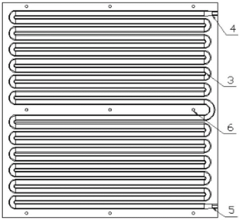
[0026] The present invention is described in detail below in conjunction with accompanying drawing: Figures 3 to 7 As shown, the finned heat exchange tube of the present invention is composed of A base tube fin 1, B base tube fin 2, heat exchange tube flow channel 3, inlet connection port 4, outlet connection port 5, and reinforcement hole 6, The A base tube fins 1 and B base tube fins 2 are base tube fins with the same shape, which constitute a half-width structure of an integral finned heat exchange tube; the A base tube fins 1, B The base tube fins 2 are respectively designed with S-shaped continuous smooth semi-structured heat exchange tube flow channels 3, and the area outside the heat exchange tube flow channel 3 is designed as fins 10 on the extended surface of the heat exchange tube flow channel 3; The fins 1 of the base tube of A and the fins 2 of the base tube of B are symmetrically distributed, and are molded and vacuum brazed to form an integral finned heat exchan...


PUM


Abstract

The invention relates to a finned heat exchange pipe formed through die pressing and vacuum brazing. The finned heat exchange pipe is composed of base pipe fins A, base pipe fins B, heat exchange pipe runners, an inlet connecting pipe opening, an outlet connecting pipe opening and strengthening holes. The base pipe fins A and the base pipe fins B are base pipe fins the same in shape and are of a semi-range structure forming the integrated finned heat exchange pipe. The S-shaped continuous and smooth semi-range structure heat exchange pipe runners are designed inside the base pipe fins A and the base pipe fins B. Fins on the expanding surfaces of the heat exchange pipe runners are designed outside the areas of the heat exchange pipe runners. The base pipe fins A and the base pipe fins B are symmetrically distributed and are formed into the integrated finned heat exchange pipe through die pressing and vacuum brazing. The S-shaped continuous and smooth heat exchange pipe runners are combined in the integrated finned heat exchange pipe. The finned heat exchange pipe has the beneficial effects of being high in heat exchange efficiency, good in forming quality, reasonable in cost and easy to produce and has high implementation value.

Description

technical field [0001] The invention belongs to the technical field of refrigeration and air-conditioning equipment, and in particular relates to a heat exchange tube with fins formed by molding and vacuum brazing. Background technique [0002] Condensers are mainly divided into three types: air-cooled, water-cooled and air-water hybrid. The evaporative condenser uses the unsaturated evaporation of the spray water film distributed on the surface of the heat exchanger, and uses the evaporation latent heat of water to take away the heat inside the heat exchanger. The fluid has more heat, and after heat and mass exchange with the passing air, the heat is finally taken away by the air. Compared with the air-cooled type, the evaporative condenser can save more than 30% of electricity, and the water consumption is only 5% of that of the ordinary water-cooled condenser. It can be seen that the evaporative condenser has significant advantages in saving electricity and water. Food, ...

Claims


Application Information

Patent Timeline
Patent Type & Authority Applications(China)
IPC IPC(8): F28F1/12F28F1/22
CPCF28F1/124F28F1/22
Inventor 陈俊健龙清泳陈俊秀
Owner ZHEJIANG SINOKING AIR CONDITIONING & REFRIGERATION CO LTD
Why Eureka
Try Eureka