Time domain finite-difference method implemented by using digital signal processing technique
A technology of finite difference in time domain and digital signal processing, which is applied in the direction of digital differential analyzer, calculation using non-numerical representation, etc., can solve the problem of increasing calculation time and achieve the effect of improving calculation efficiency
- Summary
- Abstract
- Description
- Claims
- Application Information
AI Technical Summary
Problems solved by technology
Method used
Image
Examples
example 1
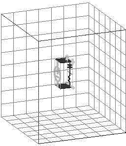
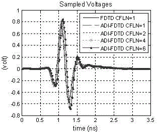
[0040] example 1. figure 2 The schematic diagram of the low-frequency RLC circuit is given, and its voltage time-domain distribution and corresponding transfer function are calculated respectively by using the method of the present invention and the traditional finite-difference method in time domain.
[0041] In order to realize the frequency domain analysis of the circuit, it is generally realized by using modulated Gaussian pulse and the like as the excitation source. set up L =10nH inductance, C =10pF capacitance series circuit, and add the internal resistance as R =50Ω voltage source excitation, using the method proposed by the present invention to carry out simulation calculations on this circuit, because the size of the circuit is small, no absorption boundary conditions are set on the calculation area, the total calculation area size is 9 × 9 × 9, Yee element cell size Δ x =Δ y =Δ z =1mm, the simulated circuit components (i.e., inductors, capacitors, and resisto...
example 2
[0044] Example 2. Figure 5 A structure diagram of a microwave low-pass filter is given, and its reflection coefficient is calculated by using the method of the present invention and the traditional finite-difference method in time domain S 11 Curves and Transmission Coefficients S 21 curve.
[0045] This low-pass filter structure belongs to microwave circuits. Set the total size of the calculation area to 76×72×30, set the coordinate stretching and perfect matching layer on the truncated boundary, and its boundary fixed parameters are respectively n pml =3; σ factor =1.3; kappa max =7; α max =7; α min =0; after adding the setting of the boundary conditions, the structure of the low-pass filter is placed in the center of the calculation area, and the method proposed by the present invention is used to carry out electromagnetic simulation on this structure to obtain the reflection coefficient of the low-pass filter S 11 Curves and Transmission Coefficients S ...
example 3
[0048] Example 3. Utilize method of the present invention and traditional time domain finite difference method, calculate dipole respectively at observation point as r =10 δ , θ = 90° electric field with time and error conditions.
[0049] Radiation field of dipole in time domain
[0050]
[0051] Since the current density is introduced in the calculation process, the dipole moment p and current density J Relationship
[0052]
[0053] Because the Yee cell is used as the basic unit, it may be assumed that the Yee cell is a cube, and the length of each side is δ , the above formula can be changed to:
[0054]
[0055] Let the dipole edge z axial vibration, and the dipole consists only of the electric field component E z Generated, using Maxwell's curl formula, the discrete scheme of the finite-difference time domain method can be obtained:
[0056]
[0057] Let the dipole radiation source be ,in T =2ns, the observation point can be obtained as r...
PUM
 Abstract
Description
Claims
Application Information
 - R&D
- Intellectual Property
- Life Sciences
- Materials
- Tech Scout
- Unparalleled Data Quality
- Higher Quality Content
- 60% Fewer Hallucinations
Browse by: Latest US Patents, China's latest patents, Technical Efficacy Thesaurus, Application Domain, Technology Topic, Popular Technical Reports.
© 2025 PatSnap. All rights reserved.Legal|Privacy policy|Modern Slavery Act Transparency Statement|Sitemap|About US| Contact US: help@patsnap.com


