
A measuring scale, its manufacturing method and using method

A technology for measuring rulers and markings, which is applied in the direction of instruments, nonlinear optics, optics, etc. It can solve the problems of electric field distribution changes, lack of high-precision detection equipment, and graphic interference, so as to eliminate measurement equipment errors and facilitate abnormal tracking. The effect of eliminating precision errors

Active Publication Date: 2019-01-04
NANJING CEC PANDA LCD TECH
View PDF10 Cites 0 Cited by
  • Summary
  • Abstract
  • Description
  • Claims
  • Application Information

AI Technical Summary

Problems solved by technology

The deviation of the line width will lead to abnormalities of various electrical characteristics; the deviation of the coincidence accuracy will cause the interference of the pattern, the change of the electric field distribution, and the generation of additional parasitic capacitance and other abnormalities
[0004] The production line of array substrates generally uses high-precision testing equipment for such parameters that require high precision. Although the precision and stability are high for mass product monitoring, the precision of the equipment will be added to the measurement results. In the middle, and there is no special high-precision detection equipment in the back section, the analysis of the broken panel needs to use off-line equipment such as microscopes, which is troublesome and has a large precision deviation.
In addition, for experiments, it is necessary to join the automation system and wait in line with mass products for measurement, which also consumes a lot of unnecessary time

Method used


Image

  • A measuring scale, its manufacturing method and using method
  • A measuring scale, its manufacturing method and using method
  • A measuring scale, its manufacturing method and using method

Examples


Embodiment Construction

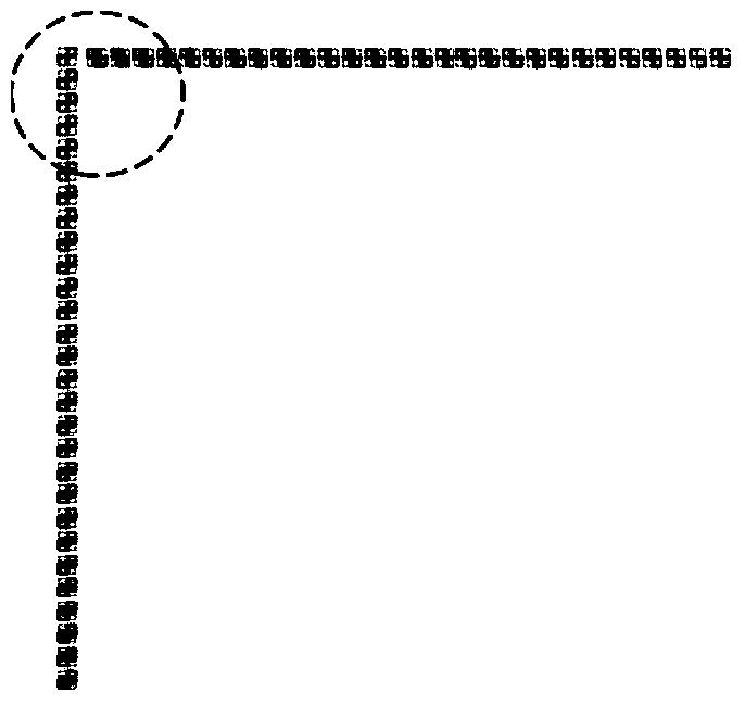
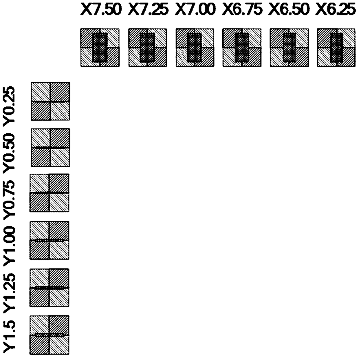
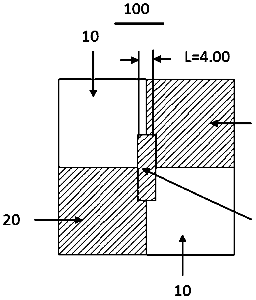
[0031] As shown in Figure 1(a) and Figure 1(b), according to the manufacturing process of the array substrate or color filter substrate, the present invention sets a measuring scale outside the pixel area of ​​the array substrate or color filter substrate, and the measuring scale is used to measure the The line width (CD) unilateral etching amount of each layer material of the substrate or the color filter substrate and the offset value of the overlay accuracy (Overlay) between each layer material, the line width (CD) can be directly read visually through the measurement scale The amount of unilateral etching and the offset value of the overlay accuracy (Overlay) between the materials of each layer can achieve the purpose of visual inspection.

[0032] Wherein, the array substrate also includes an LTPS (low temperature polysilicon technology) substrate, an IGZO (metal oxide) substrate, and an OLED substrate.

[0033] The measuring scale includes an X-direction measuring scale ...


PUM


Abstract

The invention provides a measurement scale and a manufacturing method and a using method thereof. The measurement scale is located outside a pixel region of an array substrate or a colored film substrate and comprises multiple graphic marks, wherein the graphic marks are formed by the material for any two layers of patterns of the array substrate or the colored film substrate, and deviation values of the line-width unilateral etching amounts of the two patterns and the coincident accuracy between the two patterns are visualized through the measurement scale. By combining with a pattern forming mechanism on the array substrate or the colored film substrate in the manufacturing process, the measurement scale located outside the pixel region is manufactured. The measurement scale adopts a contrasting method rather than an absolute scale for measurement, the accuracy error problem of the absolute scale itself is eliminated, and the specific deviation values of the line-width unilateral etching amounts and the coincident accuracy can be directly read out. The measurement scale can be used for any engineering section before or after etching, device measurement errors are eliminated, and abnormal tracking and test implementation are facilitated.

Description

technical field [0001] The invention belongs to the manufacturing field of liquid crystal display panels, and in particular relates to a measuring scale used for line width and coincidence accuracy, a manufacturing method and a using method. technical background [0002] The liquid crystal display panel includes an array substrate and a color filter substrate bonded together, and a liquid crystal sandwiched between the array substrate and the color filter substrate. The array substrate is provided with a plurality of criss-cross data lines and gate lines connected to the A TFT switch at the intersection of the data line and the gate line, and a plurality of pixel units formed by the intersection of the data line and the gate line. [0003] During the manufacturing process of liquid crystal display panels, due to the instability of equipment, materials and personnel, the accuracy will be shifted, and the deviation of related parameters and design values ​​will cause various p...

Claims


Application Information

Patent Timeline
Patent Type & Authority Patents(China)
IPC IPC(8): G02F1/13
CPCG02F1/1309
Inventor 刘文雄王鸣昕
Owner NANJING CEC PANDA LCD TECH
Learn More