A kind of preparation method of LED light engine packaging structure

A packaging structure, LED light source technology, applied to the circuit layout on the support structure, the circuit layout on the insulating board, and the modification through conduction and heat transfer, etc., can solve the problem of high cost, low integration, and large size of semiconductor devices. problems, to achieve the effect of improving production efficiency, improving integration and small size

Active Publication Date: 2018-08-28
中山市盈伸电子科技有限公司
View PDF5 Cites 0 Cited by
  • Summary
  • Abstract
  • Description
  • Claims
  • Application Information

AI Technical Summary

Problems solved by technology

[0004] 1) The semiconductor devices used in LED drive power supply are large in size and not highly integrated
[0005] 2) Most of the semiconductor packaging devices used in LED drive power are black, which affects the light quality of the LED light engine
[0006] 3) The heat dissipation channel of the semiconductor chip used in the semiconductor packaging device used by the LED drive power supply is relatively directly packaged on the application substrate with a high thermal resistance, which is not conducive to heat dissipation
[0007] 4) The LED drive power directly uses packaged semiconductor packaging devices, and the cost is relatively high

Method used


Image

  • A kind of preparation method of LED light engine packaging structure
  • A kind of preparation method of LED light engine packaging structure
  • A kind of preparation method of LED light engine packaging structure

Examples


Embodiment 1

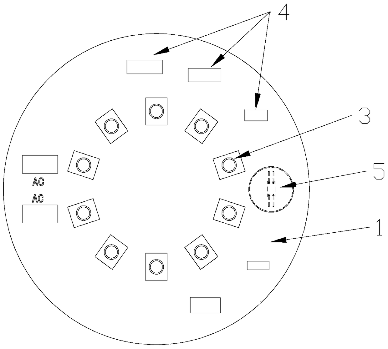
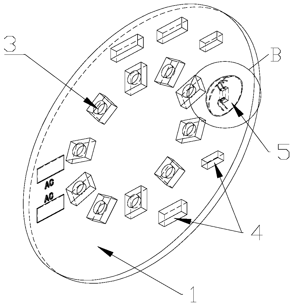
[0060] Example 1 ( figure 1 , 2 、3)

[0061]For the light engine made of SMD, EMC, CSP, Wicop patch type LED light source patch, semiconductor chip packaging can be carried out first, and then the LED light source patch can be mounted. The specific process is as follows:

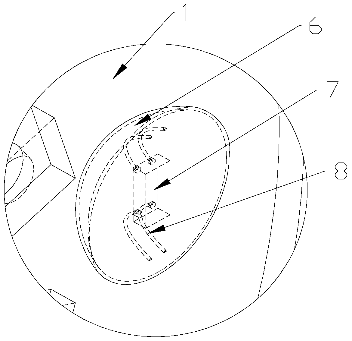
[0062] Die Bonding Use die bonding glue to fix the semiconductor wafer 7 on the die bonding position of the application substrate 1 . The die-bonding glue here can be selected according to the heat dissipation and shear force requirements of the semiconductor chip, and can be silver glue, epoxy-based insulating glue, silicon-based insulating glue, etc.

[0063] Wire bonding The semi-finished product after crystal bonding is connected to the circuit channel of the semiconductor chip 7 and the application substrate 1 through the guide wire 8 . The guide wire can be gold wire, alloy wire, copper wire, aluminum wire.

[0064] Glue Sealing Use the glue material 6 to seal and protect the semiconductor chip 7 ...

Embodiment 2

[0067] Example 2 ( Figure 4 , 5 、6)

[0068] For the light engine manufactured by the COB type LED light source chip and the LED light source chip is a front-mount chip, the packaging of the semiconductor chip and the packaging of the LED light source chip can be performed simultaneously. The specific process is as follows:

[0069] Die-bonding Use die-bonding glue to fix the semiconductor wafer 7 and the wafer of the COB type LED light source 2 on the die-bonding position of the application substrate 1 . The die-bonding glue here can be selected according to the heat dissipation and shear force requirements of the semiconductor chip, and can be silver glue, epoxy-based insulating glue, silicon-based insulating glue, etc.

[0070] Wire bonding The semi-finished product after crystal bonding is connected to the semiconductor chip 7, the chip of the COB type LED light source 2 and the circuit channel of the application substrate 1 through the guide wire 8 respectively. The ...

Embodiment 3

[0074] Embodiment 3 ( Figure 4 , 5 、6)

[0075] For a light engine made of a COB type LED light source chip and the LED light source chip is a flip chip, the packaging of the semiconductor chip and the packaging of the LED light source chip can be performed simultaneously. The specific process is as follows:

[0076] Die-bonding 1 uses a conductive material to connect and fix the chip electrode of the COB LED light source 2 with the circuit on the application substrate 1 . The conductive material can be silver glue, solder paste, AuSn alloy and other eutectic solders.

[0077] Die-bonding 2 uses die-bonding glue to fix the semiconductor wafer 7 on the die-bonding position of the application substrate 1 . The die-bonding glue here can be selected according to the heat dissipation and shear force requirements of the semiconductor chip, and can be silver glue, epoxy-based insulating glue, silicon-based insulating glue, etc.

[0078] Wire bonding The semi-finished product af...


PUM


Abstract

The invention discloses an LED optical engine encapsulation structure. An LED optical engine includes an application substrate, an LED light source as well as surface-mounted components and semiconductor chips which form an LED driving power source. The LED optical engine encapsulation structure can be realized by a process in which the LED light source as well as the surface-mounted components and the semiconductor chips which form the LED driving power source are encapsulated on the application substrate, wherein the semiconductor chips include an IC chip, a diode chip and / or a triode chip which form the LED driving power source. According to the LED optical engine encapsulation structure of the invention, the semiconductor chips are directly encapsulated on the application substrate, so that the size of the encapsulated semiconductor chips is small, so that improvement of integration can be benefitted; original encapsulation thermal resistance can be reduced, and heat dissipation performance can be improved; and cost for ICs, diodes and triodes adopted in a traditional process can be correspondingly decreased.

Description

technical field [0001] The invention relates to a preparation method of an LED light engine packaging structure. Background technique [0002] LED light engine consists of LED light source and LED driving power on the application substrate. In the current manufacturing process of LED light engines, LED drive power usually uses packaged semiconductor components (including ICs, diodes, and triodes), which are assembled through SMT processes. [0003] The disadvantages of the current LED light engine are: [0004] 1) The semiconductor devices used in the LED drive power supply are large in size and not highly integrated. [0005] 2) Most of the semiconductor packaging devices used in the LED drive power supply are black, which affects the light quality of the LED light engine. [0006] 3) In the semiconductor packaging device used by the LED drive power supply, the heat dissipation channel of the semiconductor chip is relatively directly packaged on the application substrate...

Claims


Application Information

Patent Timeline
Patent Type & Authority Patents(China)
IPC IPC(8): H01L33/52H05K7/06H05K7/20
CPCH01L33/52H05K7/06H05K7/2039
Inventor 王天柱王晓天
Owner 中山市盈伸电子科技有限公司
Why Eureka
Try Eureka