
A mill or calender roller and its manufacturing method

A calender and open mill technology, applied in the field of open mill or calender roll, open mill or calender roll manufacturing field, can solve the problem of limited water channel feasibility, high processing cost, roll elastic modulus Small problems such as improving heat transfer effect and uniformity of temperature distribution, reducing processing difficulty and cost, and uniform heating or cooling

Active Publication Date: 2018-01-26
青岛首科新材料有限公司
View PDF4 Cites 0 Cited by
  • Summary
  • Abstract
  • Description
  • Claims
  • Application Information

AI Technical Summary

Problems solved by technology

[0003] In the prior art, a medium flow channel is set in the roller to heat or cool the rubber material. The rollers in the traditional mill or calender mostly adopt two temperature control methods: hollow type and drilled type. It is chilled cast iron with high surface hardness and good wear resistance, but it has the following defects: 1. The chilled cast iron material has high brittleness, poor internal toughness, and insufficient strength. It is prone to fracture when the lateral pressure is large; Rollers made of cast iron have small elastic modulus, poor rigidity, and large deformation under lateral pressure; 3. The heat exchange effect of hollow rollers is poor, and drilled rollers need to process deep holes and inclined holes, which is difficult to process Large, high processing cost, general cooling effect, can not guarantee the uniformity of roller temperature distribution, and the integral structure limits the feasibility of processing water channels with better heat transfer effect

Method used


Image

  • A mill or calender roller and its manufacturing method
  • A mill or calender roller and its manufacturing method

Examples


Embodiment Construction

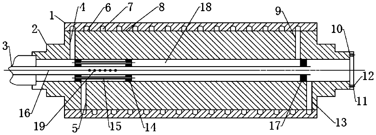
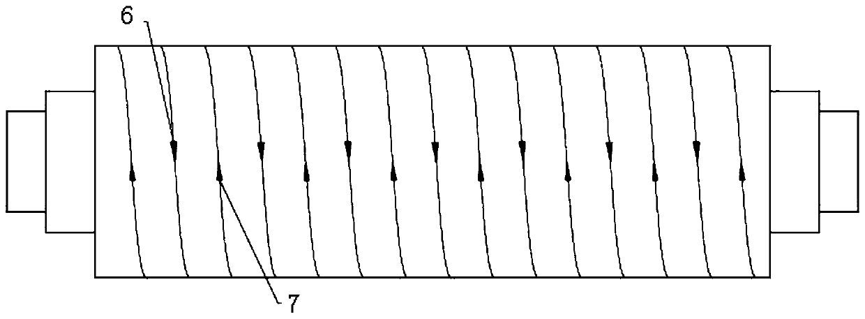
[0025] Attached below Figure 1~2 The specific embodiment of the present invention will be further described in detail.

[0026] Such as figure 1 As shown, a mill or calender roller includes a roller shaft core 2 and a roller jacket 1 sheathed together. The roller jacket 1 is made of chilled cast iron or alloy chilled cast iron, and the surface layer is white Mouth layer. The roller shaft core 2 is made of 45 steel or 40Cr or 40MnB. The roller jacket 1 and the roller shaft core 2 are connected by an interference fit through a shrink-fit method. The outer surface of the roller shaft core 2 is provided with a sealant, such as the sealant layer 8 shown in the figure, to prevent medium leakage.

[0027] The shaft center of the roller shaft core 2 is provided with a through hole 18 as the main channel, and the through hole 18 is provided with a liquid inlet pipe 16 and a diversion and return device. The inner surface of the roller jacket 1 is provided with two One end of the s...


PUM

PropertyMeasurementUnit
elastic modulusaaaaaaaaaa

Abstract

The invention discloses a roller of an open mill or a calendaring machine and a manufacturing method of the roller. The roller comprises a roller shaft core and a roller jacket, wherein the roller shaft roller is sleeved with the roller jacket. The roller jacket is made of chilled cast iron or alloy chilled cast iron. The roller shaft core is made of 45 steel or 40Cr or 40MnB. A through hole is formed in the position of the axis of the roller shaft core to serve as a main runner. A liquid inlet pipe and a flow distributing and returning device are arranged in the through hole. Two medium runners located in the roller jacket are formed between the roller jacket and the roller shaft core and communicate with the main runner through the flow distributing and returning device. The roller is good in surface abrasion resistance, good in rigidity, high in strength, remarkable in heat exchange effect and uniform in temperature distribution.

Description

technical field [0001] The invention relates to the technical field of mills and calenders, in particular to a roller of a mill or a calender, and a method for manufacturing the roller of a mill or a calender. Background technique [0002] The mill and calender are important equipment in the field of rubber processing and are widely used. The mill is mainly used for the mixing of rubber materials. The calender compacts and stretches the mixed rubber. The roller is the mill The main parts of the calender and calender will be corroded and frictioned by the rubber material and the large lateral pressure during work. In order to ensure the processing accuracy of the product, the roller must have sufficient strength, rigidity and high Surface hardness and wear resistance. According to different process requirements, the roller needs to heat or cool down the rubber when rolling the rubber. Since a large amount of heat is generated during the interaction between the rubber materi...

Claims


Application Information

Patent Timeline
Patent Type & Authority Patents(China)
IPC IPC(8): B29B7/62B29B7/82B29C43/46B29C43/52B23P15/00
CPCB23P15/00B29B7/625B29C43/46B29C43/52
Inventor 曾宪奎郝建国焦淑莉褚福海苗清
Owner 青岛首科新材料有限公司
Learn More