Steam cracking method

A cracking furnace and dilution steam technology, applied in the field of steam cracking, can solve problems such as coking in the convection section, and achieve the effect of increasing the heating rate and the selectivity.

Inactive Publication Date: 2016-06-01
CHINA PETROLEUM & CHEM CORP +1
View PDF8 Cites 6 Cited by
  • Summary
  • Abstract
  • Description
  • Claims
  • Application Information

AI Technical Summary

Problems solved by technology

[0016] The purpose of the present invention is to provide a new steam cracking method in order to overcome the problem that unsatu

Method used


Image

  • Steam cracking method
  • Steam cracking method
  • Steam cracking method

Examples


Embodiment 1

[0057] This example is used to illustrate the steam cracking method provided by the present invention.

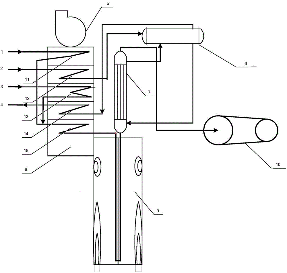
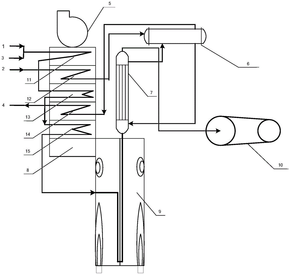
[0058] use figure 2 The cleavage equipment shown performs the cleavage reaction. The specific process includes:

[0059] The olefins of C4, C5 and C6 (the compositions are shown in Table 1) are vaporized in a vaporizer;

[0060] The mixed gas of the vaporized gas-phase unsaturated hydrocarbons 1 and the dilution steam 3 is preheated in the convection section of the cracking furnace through the raw material preheating section 11 and the mixed heating section 15, and the unsaturated hydrocarbons 1 and the dilution steam are preheated. The weight ratio of the amount of 3 is 1:0.4; then the mixed gas of the gas-phase unsaturated hydrocarbons and the dilution steam preheated by the raw material preheating section 11 and the mixed heating section 15 is used as the cracking raw material mixture; then the cracking raw material is used. The mixture is introduced into the radiant...

Embodiment 2

[0081] This example is used to illustrate the steam cracking method provided by the present invention.

[0082] The cracking reaction of unsaturated hydrocarbons is carried out according to the same method as in Example 1, except that the middle part of the radiant section of the cracking furnace is at 1 / 2 of the height of the cracking furnace, and the outlet of the radiant section of the cracking furnace is The section is on top of the radiant section of the cracking furnace.

[0083] Other process parameters of the cracking furnace are shown in Table 2;

[0084] Through the separation and analysis of the cracked gas, the composition of the cracked gas is shown in Table 5.

[0085] table 5

[0086] yield

Embodiment 3

[0088] This example is used to illustrate the steam cracking method provided by the present invention.

[0089] The cracking reaction of unsaturated hydrocarbons is carried out according to the same method as in Example 1, except that the middle part of the radiant section of the cracking furnace is at 3 / 5 of the height of the cracking furnace, and the outlet of the radiant section of the cracking furnace is The section is at the bottom of the radiant section of the cracking furnace.

[0090] Through the separation and analysis of the cracked gas, the composition of the cracked gas is shown in Table 6.

[0091] Table 6

[0092] yield


PUM


Abstract

The invention discloses a steam cracking method. The method is enforced in a vaporization device and a cracking furnace, the cracking furnace comprises a convection section and a radiation section, and the method comprises the following steps: vaporizing unsaturated hydrocarbons in the vaporization device, mixing the vaporized gaseous unsaturated hydrocarbons with dilution steam, preheating the above obtained cracking raw material mixture to the convection section of the cracking furnace, introducing the preheated cracking raw material mixture from the middle position of the radiation section of the cracking furnace, and carrying out a cracking reaction, wherein the middle position of the radiation section of the cracking furnace is the 1/4-4/5 position of the height of the cracking furnace. The cracking raw material is preheated in the convection section to a certain temperature, and the preheated cracking raw material directly enters the cracking furnace from the middle position of the radiation section of the cracking and undergoes the cracking reaction, so the heating speed of the cracking raw material in a cracking furnace tube is improved in order to improve the selectivity of the cracking reaction, thereby the yield of ethylene, propylene and butadiene is substantially improved.

Description

technical field [0001] The present invention relates to a steam cracking method. Background technique [0002] Low-carbon olefins such as ethylene, propylene and butadiene are important basic raw materials for the petrochemical industry. The current method for producing light olefins is mainly based on the tubular furnace petroleum hydrocarbon steam cracking process. According to statistics, about 99% of ethylene, more than 50% of propylene and more than 90% of butadiene in the world are produced through this process. [0003] There are two main sources of raw materials for the production of low-carbon olefin products such as ethylene, propylene and butadiene. One is the light hydrocarbons produced by natural gas, such as ethane, propane, butane and natural gasoline; the other is the processing of oil refining units. products, such as refinery gas, naphtha, diesel and secondary processed products, such as coking hydrogenated naphtha, hydrogenated tail oil, etc. A common fe...

Claims


Application Information

Patent Timeline
IPC IPC(8): C07C4/04C07C11/04C07C11/06C07C11/16
Inventor 王国清张利军张永刚周丛周先锋杜志国巴海鹏张兆斌
Owner CHINA PETROLEUM & CHEM CORP
Why Eureka
Try Eureka