Treatment equipment, treatment system and treatment method for enabling drilling fluid not to fall to ground

A technology for processing equipment and drilling fluid, which is applied in the direction of earthwork drilling, wellbore/well parts, etc., can solve problems such as soil compaction, insufficient liquid phase reuse, and damage to soil physical properties, so as to solve secondary pollution and facilitate trucking The effects of loading and transportation and improving the working environment

Pending Publication Date: 2016-06-01
德惠同利(北京)石油技术服务有限公司
View PDF9 Cites 8 Cited by
  • Summary
  • Abstract
  • Description
  • Claims
  • Application Information

AI Technical Summary

Problems solved by technology

Disadvantages: 1. The solid phase is solidified by cement, which destroys the physical properties of the soil and causes soil compaction
2. The liquid phase separation is not complete, and the final product of the liquid phase is low-density drilling fluid, which will cause poor control of the solid content of the drilling fluid
Disadvantage: The liquid phase cannot be reused
[0015] Based on many problems in the existing technology, the applicant has developed the first generation of drilling fluid non-falling equipment, which has been widely used, but its chemical treatment has no mature gel breaking method, and there is no reasonable solution to the solid phase produced in each stage. The treatment method and sewage oxidation are also difficult to meet the standards. In addition, the equipment is complicated and cumbersome and cannot be fully automated and integrated, and the liquid phase reuse is not sufficient.

Method used


Image

  • Treatment equipment, treatment system and treatment method for enabling drilling fluid not to fall to ground
  • Treatment equipment, treatment system and treatment method for enabling drilling fluid not to fall to ground
  • Treatment equipment, treatment system and treatment method for enabling drilling fluid not to fall to ground

Examples


Embodiment Construction

[0048] The present invention will be described in detail below according to the accompanying drawings, which is a preferred embodiment among various implementations of the present invention.

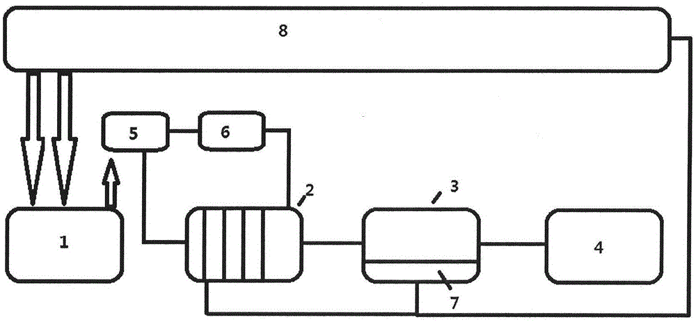
[0049]In a preferred embodiment, a drilling fluid non-landing processing equipment includes a collection unit 1, a chemical treatment unit 2, a solid-liquid separation unit 3, a crushing oxidation unit 4, a mixer 5 and a vibrating screen 6, and the collection unit 1 includes The feeding device and the discharging device, the feeding device is connected to the solid control equipment 8 and collects materials from the solid control device 8, the discharging device is connected to the chemical processing unit 2 and transports the material to the chemical processing unit 2; the chemical processing unit 2 includes device and flocculation device, which receive the material transported by the collection unit 1 and perform gel breaking and flocculation treatment on the material; the chemical proc...


PUM


Abstract

The invention relates to treatment equipment for enabling drilling fluid not to fall to ground.The treatment equipment comprises a collecting unit (1), a chemical treatment unit (2), a solid-liquid separation unit (3), a crushing and oxidizing unit (4), a mixer (5) and a vibrating screen (6).The collecting unit (1) comprises a feeding device and a discharging device, wherein the feeding device is connected to solid control equipment (8) and is used for collecting materials from the solid control equipment (8), and the discharging device is connected to the chemical treatment unit (2) and is used for conveying the materials to the same.The chemical treatment unit (2) comprises a gel breaking device and a flocculating device, is used for receiving the materials conveyed by the collecting unit (1) and subjecting the materials to gel breaking and flocculating treatment and is connected to the solid-liquid separation unit (3) and used for conveying the treated materials to the same.The solid-liquid separation unit (3) comprises a filter pressing device, a liquid outlet device and a solid outlet device, and the solid outlet device is connected to the crushing and oxidizing unit (4) and used for conveying solid materials subjected to filter pressing treatment to the crushing and oxidizing unit (4).The crushing and oxidizing unit (4) is connected with the solid-liquid separation unit (3) and used for crushing and oxidizing the materials conveyed by the same.

Description

technical field [0001] The invention relates to the field of harmless treatment of waste, in particular to a drilling fluid non-landing treatment equipment, a treatment system and a treatment method. Background technique [0002] Abandoned drilling fluid contains drilling cuttings, clay, mud and inorganic salts, etc. These wastes have complex compositions and large changes in composition, so they are of no use value. If no treatment measures or improper measures are taken, leakage, loss, diffusion and migration of organic matter and heavy metal salts will occur, which will pollute the surrounding environment and affect the normal growth of animals and plants. In severe cases, no plants will grow for many years. If the drilling waste is landfilled after it dries naturally, it will return to the slurry again when it meets water, which will directly affect the partial soil covering of the waste mud pool and cause potential long-term damage. [0003] In recent years, environmen...

Claims


Application Information

Patent Timeline
Patent Type & Authority Applications(China)
IPC IPC(8): E21B41/00
CPCE21B41/005
Inventor 黄禾杨小平韩阳
Owner 德惠同利(北京)石油技术服务有限公司
Why Eureka
Try Eureka