
A Micro/Off-Grid Compressed Air Energy Storage System Based on Free Piston Expansion/Compressor-Linear Motor

A technology of compressed air energy storage and linear motors, applied in piston pumps, machines/engines, mechanical equipment, etc., can solve the problems of compressed air energy storage systems such as poor taste of heat energy, unadjustable compression/expansion ratio, and reduced power generation efficiency. Achieve the effect of high degree of mechatronics, reduce design cost and improve power generation efficiency

Active Publication Date: 2018-01-19
中国冶金科技成果转化有限公司
View PDF7 Cites 0 Cited by
  • Summary
  • Abstract
  • Description
  • Claims
  • Application Information

AI Technical Summary

Problems solved by technology

At the same time, due to the small flow rate of the system, traditional compressed air energy storage systems mostly use single-stage or multi-stage reciprocating compressors and turbine units, the compression / expansion ratio cannot be adjusted, the system structure is relatively complex, the cost is high, and the reliability is high. poor
At the same time, in the process of compressing energy storage, the pressure in the gas storage device gradually increases, resulting in a decrease in energy storage efficiency, and in the process of deflated power generation, the pressure of compressed air in the gas storage device gradually decreases, which in turn leads to a decrease in power generation efficiency
In addition, the compressed air energy storage system will generate a large amount of low-grade heat energy during operation, which is wasted without utilization

Method used


Image

  • A Micro/Off-Grid Compressed Air Energy Storage System Based on Free Piston Expansion/Compressor-Linear Motor
  • A Micro/Off-Grid Compressed Air Energy Storage System Based on Free Piston Expansion/Compressor-Linear Motor

Examples


Embodiment Construction

[0019] The present invention will be further described in detail below in conjunction with the accompanying drawings.

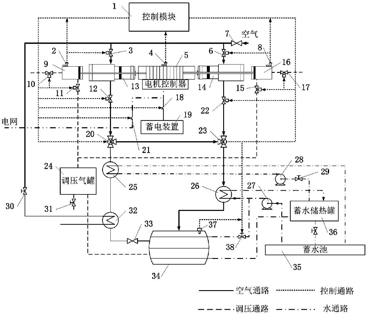
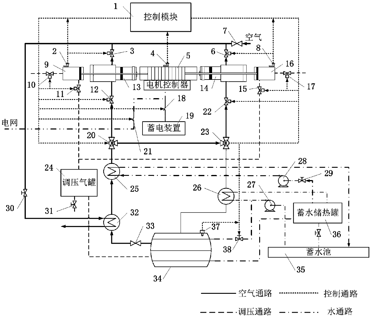
[0020] figure 1 It is a schematic diagram of the energy storage working process of the micro / off-grid compressed air energy storage system, and its connection relationship is as follows: figure 1 As shown, the above micro / off-grid compressed air energy storage system includes a control module (1), pressure sensor one (2), electric valve one (3), displacement sensor (4), linear motor (5), electric valve two (6), pressure sensor two (8), electric valve three (10), electric valve four (11), electric valve five (12), electric valve six (15), electric valve seven (17), electric valve eight ( 22), switch relay one (18), power storage device (19), electromagnetic three-way valve one (20), switch relay two (21), electromagnetic three-way valve two (23), electromagnetic valve one (30), electromagnetic Valve two (38) and corresponding connecting lines;

[0021] The ...


PUM


Abstract

The invention discloses a free piston expander / compressor-linear motor-based miniature / off-grid compressed-air energy storage system. The system comprises free piston expanders / compressors, a linear motor, pressure regulating air tanks, heat exchangers, a shell-and-tube air storage tank, water pumps, a water storage and energy storage tank, a water storage pool and corresponding connecting pipelines; a control system comprises a control module, pressure sensors, a displacement sensor, electric valves, switching relays, an electrical storage device, electromagnetic three-way valves, electromagnetic valves and corresponding connecting lines. The energy storage system can separately act as the compressors and the expanders during energy storage and power generation, so that a structure of the compressed-air energy storage system is greatly simplified, and cost is reduced; meanwhile, by adopting the shell-and-tube air storage tank and regulating an expansion / compression ratio, drastic fluctuation of pressure and temperature of compressed air in the air storage device can be reduced by the system, optimal utilization on energy of an air compression and expansion link is realized, and efficiency of the compressed-air energy storage system is increased.

Description

technical field [0001] The invention relates to the field of energy storage power generation, in particular to a micro / off-grid compressed air energy storage system. Background technique [0002] Compressed air energy storage system (CAES) is an electric energy storage system that can realize large-capacity and long-term electric energy storage. It stores excess electrical energy by compressing air, and releases high-pressure air to generate power through an expander during peak power consumption. Among them, the compressor and expander are the core components of the compressed air energy storage system, and their performance has a decisive impact on the performance of the entire system. At the same time, due to the small flow rate of the system, traditional compressed air energy storage systems mostly use single-stage or multi-stage reciprocating compressors and turbine units, the compression / expansion ratio cannot be adjusted, the system structure is relatively complex, t...

Claims


Application Information

Patent Timeline
Patent Type & Authority Patents(China)
IPC IPC(8): F04B35/04F04B41/06F04B41/02F04B49/06F04B49/22F01B23/10F01B25/10
CPCF01B23/10F01B25/10F04B35/04F04B41/02F04B41/06F04B49/06F04B49/22Y02E60/16
Inventor 李高胜张红光杨富斌宋松松常莹于飞
Owner 中国冶金科技成果转化有限公司
Learn More