
Temperature control structure used for optical microwave time-delay network

A technology of delay network and microwave, which is applied in the direction of temperature control by electric method, laser parts, etc., can solve the problems of permanent device that cannot work normally, narrow working temperature range of device, and inability to realize temperature control, etc. Control efficiency, strong anti-interference ability, and the effect of increasing temperature adaptability

Active Publication Date: 2016-06-01
LEIHUA ELECTRONICS TECH RES INST AVIATION IND OF CHINA
View PDF5 Cites 4 Cited by
  • Summary
  • Abstract
  • Description
  • Claims
  • Application Information

AI Technical Summary

Problems solved by technology

[0003] However, the development of the optical microwave delay network system faces many problems, especially the sensitivity of the optical microwave delay network system to the ambient temperature restricts its development. In the optical microwave delay network system, most of the devices are extremely sensitive to temperature. Small fluctuations in ambient temperature will have a non-negligible impact on its accuracy and stability. At the same time, the normal operating temperature range of these devices is very narrow. When the external ambient temperature is too high or too low, the optical microwave delay network system will not work normally. work or even cause permanent damage to the device
[0004] The temperature control structure of the existing optical microwave time-delay network system is generally controlled by the method of integrating semiconductor cooling chip TEC and thermistor NTC (NegativeTemperatureCoefficient) inside the optical transmitter or optical receiver, but due to the characteristics of TEC itself, When the TEC works for a long time, the heat generated by it is easy to accumulate, and a heat sink must be added, and the efficiency of the heat sink is often proportional to its volume, which increases the volume of the system; at the same time, when the external temperature is too high Or when it is too low, normal temperature control cannot be achieved due to the power limitation of the TEC

Method used


Image

  • Temperature control structure used for optical microwave time-delay network

Examples


Embodiment Construction

[0023] The invention discloses a temperature control structure of an optical microwave delay network, which realizes the stable and normal operation of the temperature control structure of the optical microwave delay network at least in the temperature range of -55 to +70.

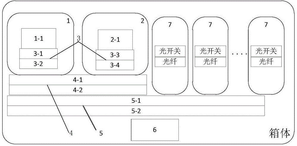
[0024] A temperature control structure of an optical microwave delay network system, including an optical transmitter 1, an optical receiver 2, and an optical delay device 7 installed in a box, the optical transmitter 1 includes an internal laser chip 1-1, and an optical receiver 2 includes an internal optical receiver chip 2-1, characterized in that it includes:

[0025] A temperature control circuit 6, used to control the first-level temperature control unit 3, the second-level temperature control unit 4 and the third-level temperature control unit 5;

[0026] The first-level temperature control unit 3 includes a first-level laser chip heating refrigerator 3-1 and a first-level laser chip temperature sen...


PUM


Abstract

The present invention provides a temperature control structure used for an optical microwave time-delay network, comprising a light emitter (1), a light receiver (2) and a light delayer (7) arranged in a box, wherein the light emitter (1) comprises a laser chip (1-1) therein, the light receiver (2) comprises a light receiver chip (2-1) therein. The temperature control structure is characterized by comprising a temperature control circuit (6) used for controlling a first stage temperature control unit (3), a second stage temperature control unit (4) and a third stage temperature control unit (5).

Description

technical field [0001] The invention relates to a temperature control structure, in particular to a three-stage temperature control structure used in an optical microwave delay network, and belongs to the technical field of temperature control. Background technique [0002] Optical microwave delay is a combination of photon and microwave technology. Optical microwave delay network has the advantages of wide bandwidth, low power consumption, small size, and no electromagnetic interference. It is widely used in various fields of national economy and national defense technology. At the same time, the optical microwave delay network is one of the core components of the optical phase control radar, which overcomes the inherent aperture effect and the limitation of the transit time of the traditional electric phase control radar, and improves the resolution, recognition ability, and solution of the radar. Multi-target imaging capability and anti-electromagnetic interference capabi...

Claims


Application Information

Patent Timeline
IPC IPC(8): H01S3/02G05D23/19
Inventor 孔德武侯付平王文睿
Owner LEIHUA ELECTRONICS TECH RES INST AVIATION IND OF CHINA
Learn More