Fatigue testing device of material under thermal-mechanical coupling effect

A fatigue test, thermal-mechanical coupling technology, used in measuring devices, analyzing materials, and testing the strength of materials using stable tension/pressure. Clamping and loading, thermal coupling fatigue test takes a long time, etc., to achieve the effect of shortening the test cycle, shortening the test cycle and shortening the heating time

Inactive Publication Date: 2016-06-08
安徽微世特机电设备有限公司
View PDF19 Cites 18 Cited by
  • Summary
  • Abstract
  • Description
  • Claims
  • Application Information

AI Technical Summary

Problems solved by technology

However, the existing fatigue testing machines only consider the effect of thermal load or mechanical load. In fact, many materials or products are subjected to the combined effect of thermal load and mechanical load in actual work. load, it will be difficult to accurately evaluate the stress state of materials or products and predict the fatigue life of materials or products
Moreover, in the prior art, the equipment is complicated, the energy consumption is high, and the heating and cooli...

Method used


Image

  • Fatigue testing device of material under thermal-mechanical coupling effect
  • Fatigue testing device of material under thermal-mechanical coupling effect
  • Fatigue testing device of material under thermal-mechanical coupling effect

Examples


Embodiment 1

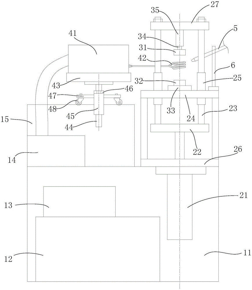
[0072] like figure 1 and figure 2 As shown, a material fatigue test device under thermal-mechanical coupling includes a test device, a control device, a loading device for providing a uniaxial tensile load or a compressive load to a sample, an induction heating coil 42 for rapid heating, and A cooling device for rapidly cooling samples, the loading device includes two upper and lower clamps and a drive mechanism 21 that drives the two clamps to move closer and away from each other, and the induction heating coil 42 is located in the test chamber formed between the two clamps. In the sample loading area, during the test, the sample is vertically placed in the induction heating coil 42. In other embodiments, the heating device can be laser heating, etc.; the cooling device is close to the sample loading area, and the thermal coupling fatigue test sample is rapidly cooled. .

[0073] The loading device also includes a support mechanism, a fixed seat 24, a movable seat 27 and a...

Embodiment 2

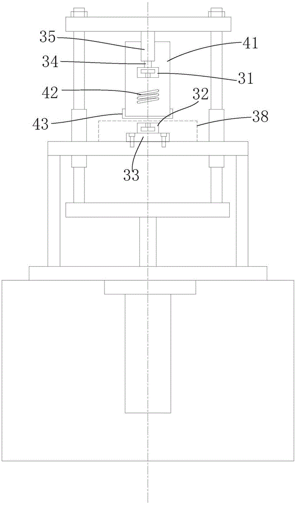
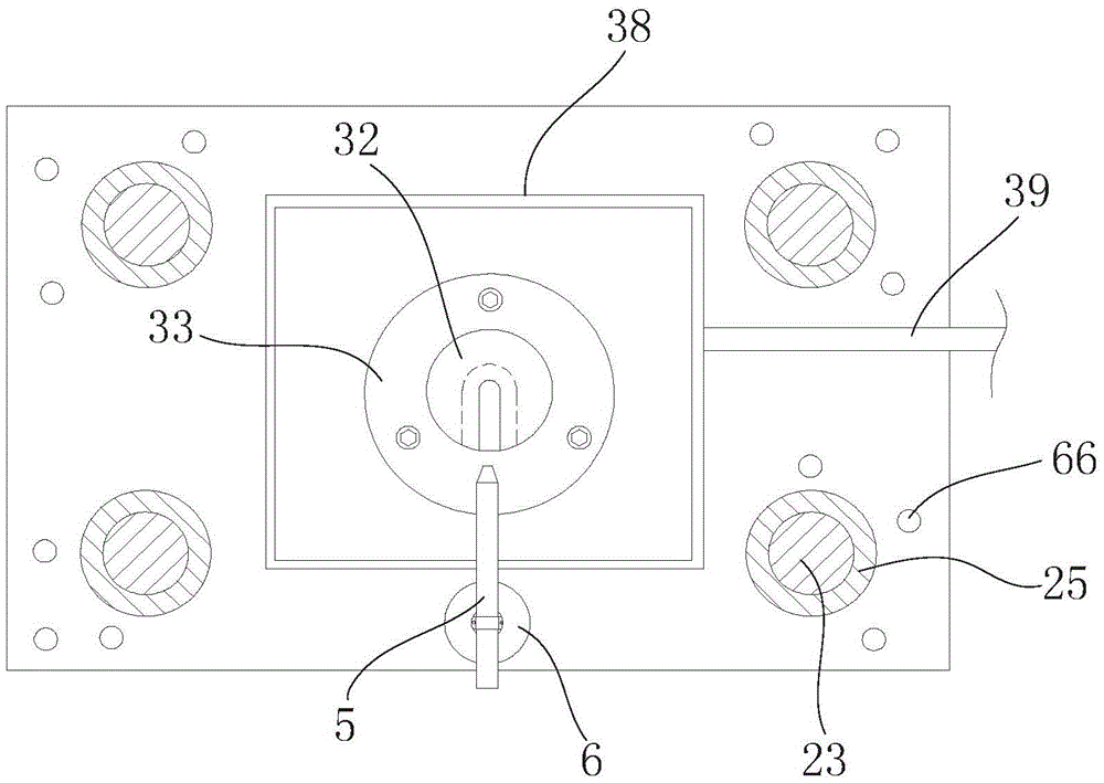
[0084] like Figure 7 Shown is another embodiment of the present invention, which is different from Embodiment 1 in that in this example, an upper clamping seat 31 is arranged on the upper surface of the support plate 22, and a load cell 34 is connected to it, and the lower surface of the fixing seat 24 is arranged A lower clamping seat 32, another sample loading area is formed between the two clamping seats, and a testing device, a cooling device, a heating device and the like are provided. Wherein the induction heating coil 42 of the lower heating device shares a high-frequency induction heating furnace 41 with the upper heating device; the two loading areas above and below the structure fixing seat simultaneously load the same sample, for example, the upper one performs tensile loading, The lower part is loaded under compression, and the two groups are carried out simultaneously with the same load and the same stroke. This can further shorten the test cycle. All the other...


PUM


Abstract

The invention provides a fatigue testing device of a material under a thermal-mechanical coupling effect. The fatigue testing device comprises a loading device used for supplying single-axis tension load or compression load to a sample, an induction heating coil used for quickly heating and a cooling device used for quickly cooling the sample, wherein the loading device comprises two clamp bases and a driving mechanism used for driving the two clamp bases to be close to each other or far from each other; the induction heating coil is located in a sample loading area formed between the two clamp bases; the cooling device is close to the sample loading area and can adopt an air-cooling manner or a water-cooling manner; clamp heads corresponding to the sample are arranged on the two clamp bases; the induction heating coil can rotate horizontally and vertically to adjust the position. The fatigue testing device provides a reasonable test environment for testing the fatigue life of the material or a product under the thermal-mechanical coupling effect, can implement the thermal-mechanical coupling fatigue test under the tension and compression states so as to more accurately predict the fatigue life of the material or the product, and is capable of quickly increasing the temperature, shortening the test period and improving the test efficiency.

Description

technical field [0001] The invention belongs to the technical field of material testing, and in particular relates to a material fatigue testing device under the action of thermomechanical coupling. Background technique [0002] The fatigue test under the thermal-mechanical coupling of materials is an effective way to accurately evaluate the performance or life of materials in practical applications. However, the existing fatigue testing machines only consider the effect of thermal load or mechanical load. In fact, many materials or products are subjected to the combined effect of thermal load and mechanical load in actual work. Load, it will be difficult to accurately evaluate the stress state of materials or products and predict the fatigue life of materials or products. Moreover, in the prior art, the equipment is complicated, the energy consumption is high, and the heating and cooling cycle is long, which leads to a long cycle of a single test. Usually, the sample has t...

Claims


Application Information

Patent Timeline
IPC IPC(8): G01N3/60G01N3/18G01N3/04
CPCG01N3/04G01N3/18G01N3/60
Inventor 唐远金孙智富孙健
Owner 安徽微世特机电设备有限公司
Why Eureka
Try Eureka