Common plant model for modelling of physical plant items of production plant

A factory model, a technology for producing factories, applied in the directions of comprehensive factory control, general control system, data processing applications, etc., which can solve problems such as error-prone and difficult integration.

Inactive Publication Date: 2016-06-08
SIEMENS AG
View PDF4 Cites 7 Cited by
  • Summary
  • Abstract
  • Description
  • Claims
  • Application Information

AI Technical Summary

Problems solved by technology

[0009] Therefore, integration between these different levels of products is difficult and error-prone due to the need to keep the different planning models consistent during engineering as well as runtime
Linking a new control function (i.e. the temperature of a device) to a new target destination in a control environment is still a significant investment so far

Method used


Image

  • Common plant model for modelling of physical plant items of production plant
  • Common plant model for modelling of physical plant items of production plant
  • Common plant model for modelling of physical plant items of production plant

Examples


Embodiment Construction

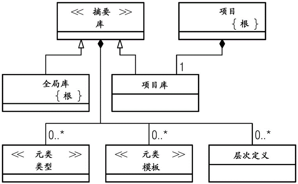
[0048] In the following, the object model of the Common Plant Model (hereinafter referred to as CPM) is described from an implementation-independent perspective. The general idea for the creation and application of the CPM is to employ a single software platform for the control and execution of the production process, where unique tasks are assigned to MES, SCADA and DCS+ systems. Customized software platforms are also referred to as projects in the following.

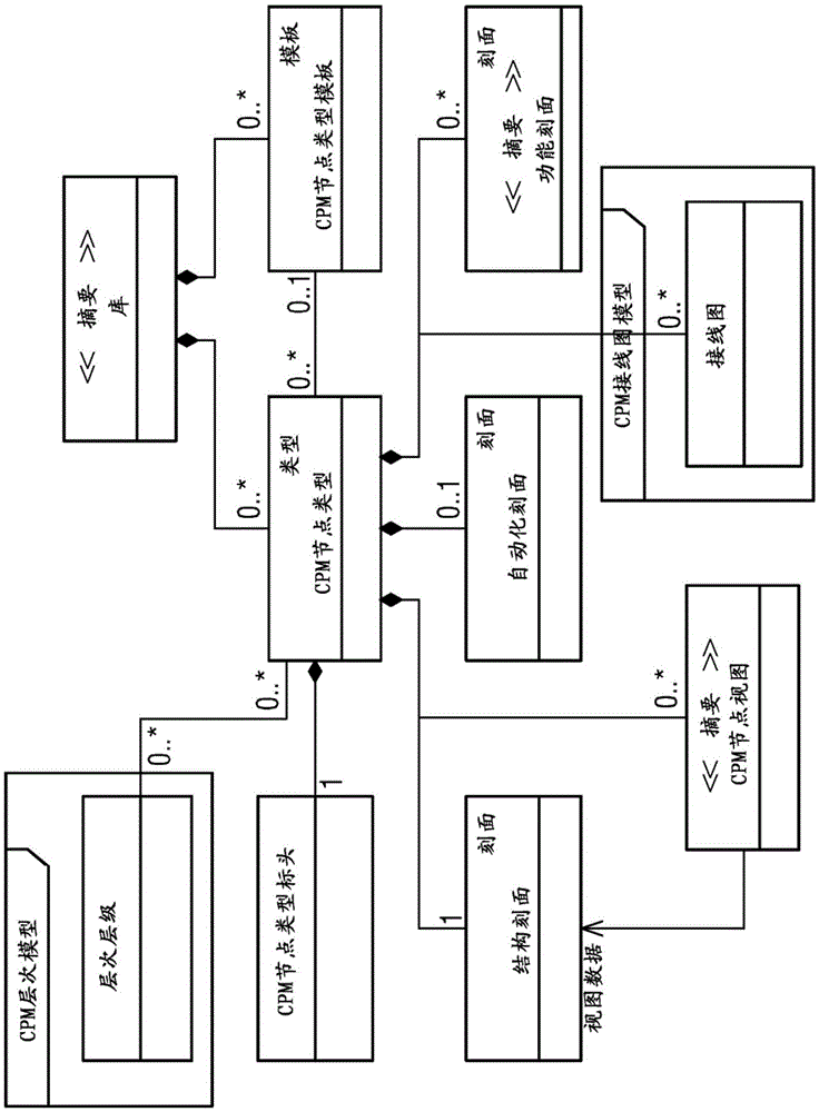
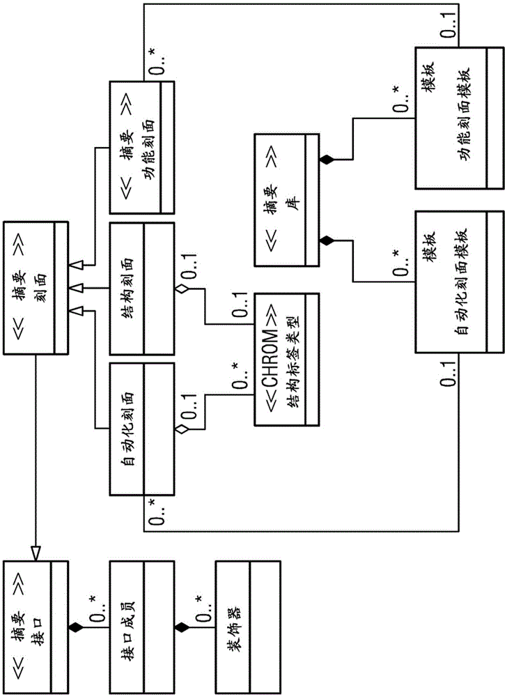
[0049] CPM is designed to model and organize every related item in a physical manufacturing plant. Physical plant items can represent fixed equipment, movable equipment, tools, assets, and so on. This specification uses the term "CPM node" for a physical plant item. The purpose of the CPM node is to aggregate different aspects for modeling a single plant entity element. This aggregation involves public interface parameters as well as automation parameters. All CPM nodes are characterized by a set of common paramet...


PUM


Abstract

The invention discloses a common plant model for modelling of physical plant items of a production plant within a manufacturing execution system having an engineering environment and a runtime environment, comprising: a) a node type model aggregating different aspects for the modelling of a single physical plant item involving public interface parameters as well as automation parameters; b) a number of nodes, each representing an instance of a node type; c) a library model comprising a project library and a global library, said libraries comprising the node type model, a facet model and a rule model as well as a hierarchy model, d) a graph model representing physical and/or logical connections between the nodes, e) a wiring chart model defining the interaction between interface members of different facets within the same node and/or among different nodes; and wherein each facet comprises at least one interface member and the logical link among the interface members is a virtual wire defining a connection used to propagate and align facet parameters which are linked to a specific node.

Description

technical field [0001] The present invention relates to a generic plant model for modeling physical plant items of a production plant within a manufacturing execution system having an engineering environment and a runtime environment. Background technique [0002] It is well known that methods for manufacturing processes planned by enterprise resource planning (ERP) and produced by the shop floor provide a manufacturing execution system (MES) for modeling, planning, scheduling and executing manufacturing processes and controlling the factory floor level corresponding production steps. In the automation pyramid consisting of levels 0 to 4, the ERP system resides at the highest level at level 4, which represents the corporate level responsible for rough production planning and purchase order processing. The MES system is at level 3, which represents the factory control level, including detailed production modeling, planning, production execution, production data acquisition, ...

Claims


Application Information

Patent Timeline
Patent Type & Authority Applications(China)
IPC IPC(8): G06Q10/06G06Q50/04
CPCG06Q10/0633G06Q10/067G06Q50/04G06Q10/06Y02P90/30G05B19/41885G05B2219/32339G05B2219/32369Y02P90/02G06F30/18
Inventor 弗兰切斯卡·多里亚詹皮耶罗·阿尔塔雷马可·切雷吉诺詹卢卡·罗西乌尔里希·布劳恩克劳斯·扬德尔奥利弗·图劳
Owner SIEMENS AG
Why Eureka
Try Eureka