Wind power converter main circuit topological structure with two units of direct-current bus connected in series

A technology of wind power converters and DC busbars, applied in AC network circuits, AC power input conversion to AC power output, circuit devices, etc. Increase and other problems, to achieve the effect of easy design and selection and systematic configuration, higher voltage level, and compact bus parallel circuit

Inactive Publication Date: 2016-06-08
GUANGDONG MINGYANG WIND POWER IND GRP CO LTD
View PDF7 Cites 5 Cited by
  • Summary
  • Abstract
  • Description
  • Claims
  • Application Information

AI Technical Summary

Problems solved by technology

[0003] Since the mainstream converters on the market today are low-voltage converters, most of the power devices used in low-voltage converters are IGBT power devices with a voltage level of 1700V. The increase in converter power and the increase in generator outlet voltage require the use of The specifications of IGBT power devices continue to increase. Due to the use principles and technical limitations of IGBT power devices, users generally can only replace IGBT power devices with larger specifications or use parallel connection of power devices. When the power increases to a certain At the same time, the volume of the converter will increase due to the parallel connection, but the space in the wind power base tower is limited, and the converter cannot be placed in the base tower

Method used


Image

  • Wind power converter main circuit topological structure with two units of direct-current bus connected in series
  • Wind power converter main circuit topological structure with two units of direct-current bus connected in series
  • Wind power converter main circuit topological structure with two units of direct-current bus connected in series

Examples


Embodiment Construction

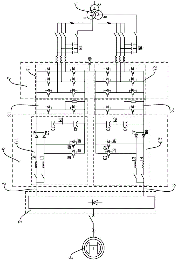
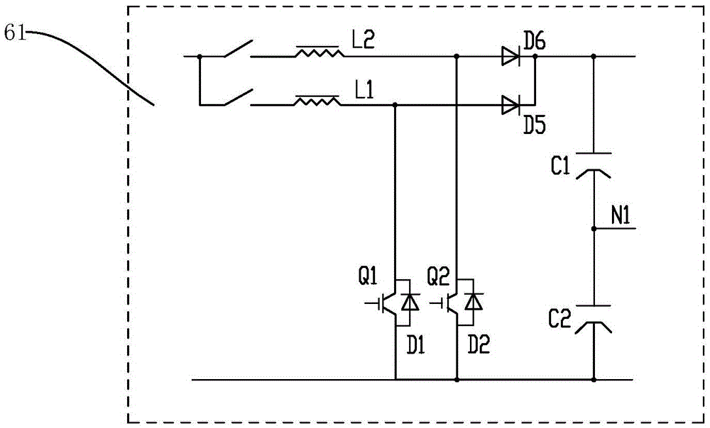
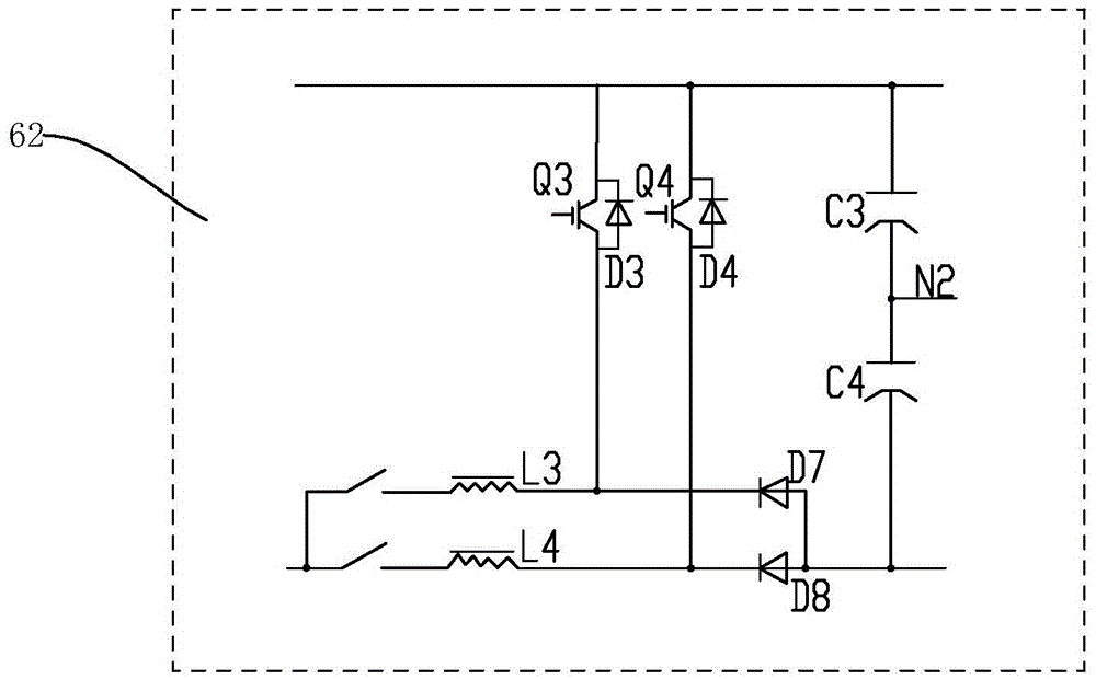
[0017] Such as figure 1 As shown, the DC bus two-unit series converter circuit of the present invention includes a generator 1, a positive bus 2, a negative bus 3, a transformer 4 connected to an external power grid, and a rectifier module 5 connected to the positive bus 2 and negative bus 3 , a step-up module 6, an inverter module 7, the input end of the rectification module 5 is electrically connected to the generator 1, the input end of the step-up module 6 is electrically connected to the output end of the rectification module 5, the step-up The output terminal of the voltage module 6 is electrically connected to the input terminal of the inverter module 7, and the output terminal of the inverter module 7 is connected to the grid in parallel with the transformer 4. The alternating current is converted into direct current, and then boosted by the step-up module 6 , and finally the direct current is converted into alternating current by the inverter module 7 , and is connect...


PUM


Abstract

The invention discloses a wind power converter main circuit topological structure with two units of a direct-current bus connected in series. The wind power converter main circuit topological structure with two units of the direct-current bus connected in series comprises a power generator, a positive bus, a negative bus, a transformer connected with an external power grid, a rectification module through which the positive bus and the negative bus are connected, a boosting module and an inversion module. The positive bus and the negative bus are connected in series after being processed by the rectification module, the boosting module and the inversion module, and a neural point is grounded. By means of the design, the wind power converter main circuit topological structure can bear higher outlet voltage of the power generator, the voltage level of the direct-current bus is improved, bus current is reduced under the same power, the wind power converter main circuit topological structure is applicable to a high-power direct-drive type wind power converter, a control mode is flexible, meanwhile, insulating difficulty is reduced, the whole structure is more compact compared with the situation that an IGBT power device or a bus parallel-connection circuit is purely replaced, the occupied area of the converter is reduced, and design and type selection and systematic configuration can be achieved easily.

Description

technical field [0001] The invention relates to a wind power converter, in particular to a main circuit topology structure of a wind power converter with two units of a direct current bus in series. Background technique [0002] With the wide application of new energy, in the field of wind power generation, in order to improve the utilization efficiency of wind power, the power of wind turbines is increasing continuously, and the increase in power brings about the corresponding increase in the output voltage and current of the generator. The demand for converter capacity is therefore constantly increasing. [0003] Since the mainstream converters on the market today are low-voltage converters, most of the power devices used in low-voltage converters are IGBT power devices with a voltage level of 1700V. The increase in converter power and the increase in generator outlet voltage require the use of The specifications of IGBT power devices continue to increase. Due to the use ...

Claims


Application Information

Patent Timeline
Patent Type & Authority Applications(China)
IPC IPC(8): H02M5/458H02J3/38
CPCH02J3/386H02M5/458Y02E10/76
Inventor 张佳丽于虹李文清李志华黎林周立专
Owner GUANGDONG MINGYANG WIND POWER IND GRP CO LTD
Why Eureka
Try Eureka