Circular steel tube constraining reinforced concrete-steel beam framework node for nodal-region composite steel tube

A technology of reinforced concrete and round steel pipes, which is applied in the direction of construction and building construction, can solve problems affecting the stability and safety of building structures, non-compliance, etc., to avoid the reduction of concrete constraint effects, improve bearing capacity and ductility, Construct simple effects

Inactive Publication Date: 2016-06-15
CHONGQING UNIV
View PDF9 Cites 18 Cited by
  • Summary
  • Abstract
  • Description
  • Claims
  • Application Information

AI Technical Summary

Problems solved by technology

[0004] The joint connection and structure directly affect the stability and safety of the building structure. The steel pipe-constrained reinforced concrete outsourcing column is disconnected in the beam-column joint area. If the joint area adopts the traditional reinforced concrete and steel beam connection structure, the steel pipe-constrained reinforced concrete column The bearing capacity is much higher than that of ordinary reinforced concrete columns of the same cross-sectional size, resulting in beam-column joints becoming weak parts, which does not comply with the design principle of "strong nodes, weak members"

Method used


Image

  • Circular steel tube constraining reinforced concrete-steel beam framework node for nodal-region composite steel tube
  • Circular steel tube constraining reinforced concrete-steel beam framework node for nodal-region composite steel tube

Examples


Embodiment Construction

[0028] The present invention will be further described below in conjunction with the accompanying drawings and embodiments, but it should not be understood that the scope of the subject matter of the present invention is limited to the following embodiments. Without departing from the above-mentioned technical ideas of the present invention, various replacements and changes made according to common technical knowledge and conventional means in this field shall be included in the protection scope of the present invention.

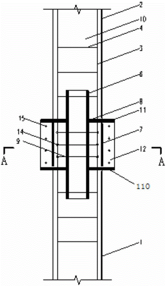
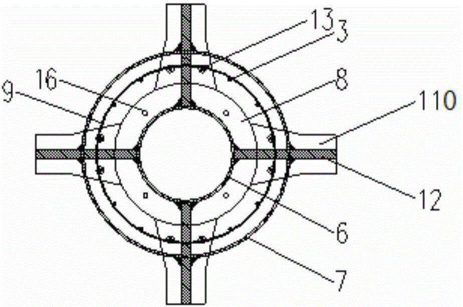
[0029] see figure 1 with figure 2 , a circular steel pipe bound reinforced concrete-steel beam frame joint with compound steel pipes in the joint area, including column round steel pipe I1, column round steel pipe II2, column longitudinal reinforcement 3, column stirrup 4, steel beam 5, and inner round steel pipe in the joint area 6. Outer round steel pipe 7 in the node area, outer reinforcing ring 8, stirrup bar 9 and concrete 10 in the node area.

[003...


PUM

PropertyMeasurementUnit
diameteraaaaaaaaaa

Abstract

The invention provides a circular steel tube constraining reinforced concrete-steel beam framework node for a nodal-region composite steel tube. The node comprises a first columnar circular steel tube, a second columnar circular steel tube, columnar longitudinal bars, columnar stirrups, a steel beam, a nodal-region inner-layer circular steel tube, a nodal-region outer-layer circular steel tube, outer reinforcing rings, nodal-region stirrups and concrete. The second columnar circular steel tube and the first columnar circular steel tube are located on the upper side and the lower side of the steel beam respectively. The steel beam directly transmits the shear force and the bending moment to the nodal-region inner-layer circular steel tube and then transmits the shear force and the bending moment to the core-region concrete, the condition that the nodal-region outer-layer steel tube directly bears the shear force is avoided to prevent the steel tube from being bent, and therefore the steel tube can fully play an annular constraining role to ensure the bearing capacity and the ductility of the node; the two ends of the nodal-region inner-layer circular steel tube stretch into an upper steel tube constraining reinforced concrete column and a lower steel tube constraining reinforced concrete column by a certain distance respectively, the integrity of the node is guaranteed, and the shear capacity and anti-seismic performance of the node are improved. The node is safe, reliable, good in integrity, clear in force transmission and convenient to construct and has the advantage on force bearing and the economic performance.

Description

technical field [0001] The invention belongs to the technical field of building structures, in particular to a circular steel pipe-constrained reinforced concrete column-steel beam frame joint. Background technique [0002] Circular steel tube confined concrete column is a new type of composite structural member proposed on the basis of steel tube concrete column to solve the problem of complex structure of its frame joints. The steel pipes of circular steel pipe-constrained concrete columns are disconnected at the beam-column joints, and concrete is poured into the steel pipes to form a steel-concrete composite vertical load-bearing member. In actual engineering, the column is generally subjected to the joint action of axial force, bending moment and shear force. Therefore, when applying the circular steel pipe confined concrete structure technology, it is necessary to arrange steel bars in the column to form a circular steel pipe confined reinforced concrete column. [00...

Claims


Application Information

Patent Timeline
Patent Type & Authority Applications(China)
IPC IPC(8): E04B1/58E04B1/30
CPCE04B1/30E04B1/58
Inventor 甘丹周绪红刘界鹏程国忠闫标
Owner CHONGQING UNIV
Why Eureka
Try Eureka