
Bonded helical compression spring

A compression spring, combined technology, applied in the field of compression springs, can solve the problems of composite material benefits such as multi-wave compression springs not fully realized, fiber and/or resin matrix cracks, fractures or failures

Inactive Publication Date: 2016-06-15
TE CONNECTIVITY CORP
View PDF0 Cites 15 Cited by
  • Summary
  • Abstract
  • Description
  • Claims
  • Application Information

AI Technical Summary

Problems solved by technology

However, the benefits of composite materials have not been fully realized in the use of multi-wave compression springs due in part to the characteristics of the waves and the forming requirements associated with the waves
Forming waves into cured composite filament layers or coil springs is impractical and will result in cracking, breaking or failure of the composite's fiber and / or resin matrix
Also, even if the cured composite wire could be edge wound like metal wire, the crests and troughs would still be skewed, causing point contact and all the defects that come with it

Method used


Image

  • Bonded helical compression spring
  • Bonded helical compression spring
  • Bonded helical compression spring

Examples


Embodiment Construction

[0016] The description of exemplary embodiments in accordance with the principles of the invention is intended to be read in conjunction with the accompanying drawings, which are considered a part of this entire specification. In the description of the embodiments of the invention disclosed herein, any reference to direction or orientation is for convenience of illustration only and does not limit the scope of the invention in any way. Related terms such as "below", "above", "horizontal", "vertical", "above", "below", "upward", "downward", "top" and "bottom" and their derivatives (such as , "horizontally", "downwardly", "upwardly", etc.) should be construed as referring to directions described in the ensuing discussion or shown in the drawings. These relative terms are for convenience of description only and do not require that those devices be constructed or operated in a particular orientation unless expressly so stated. Terms such as "attached", "fixed", "connected", "coup...


PUM


Abstract

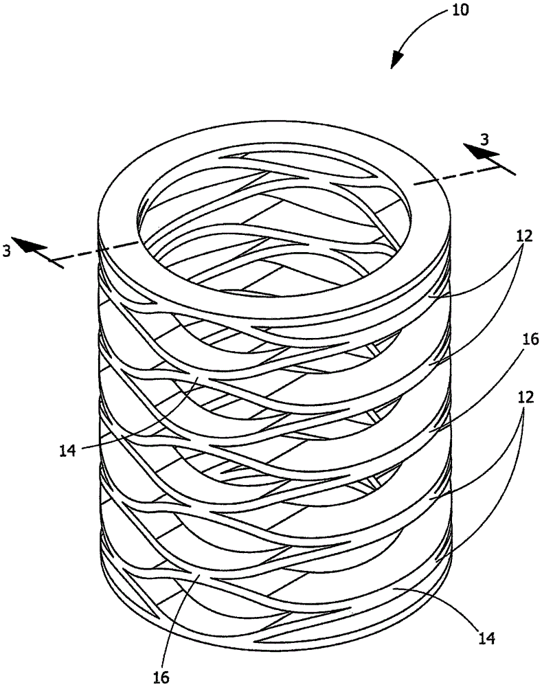
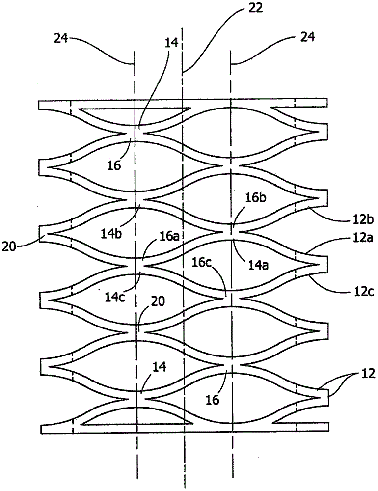
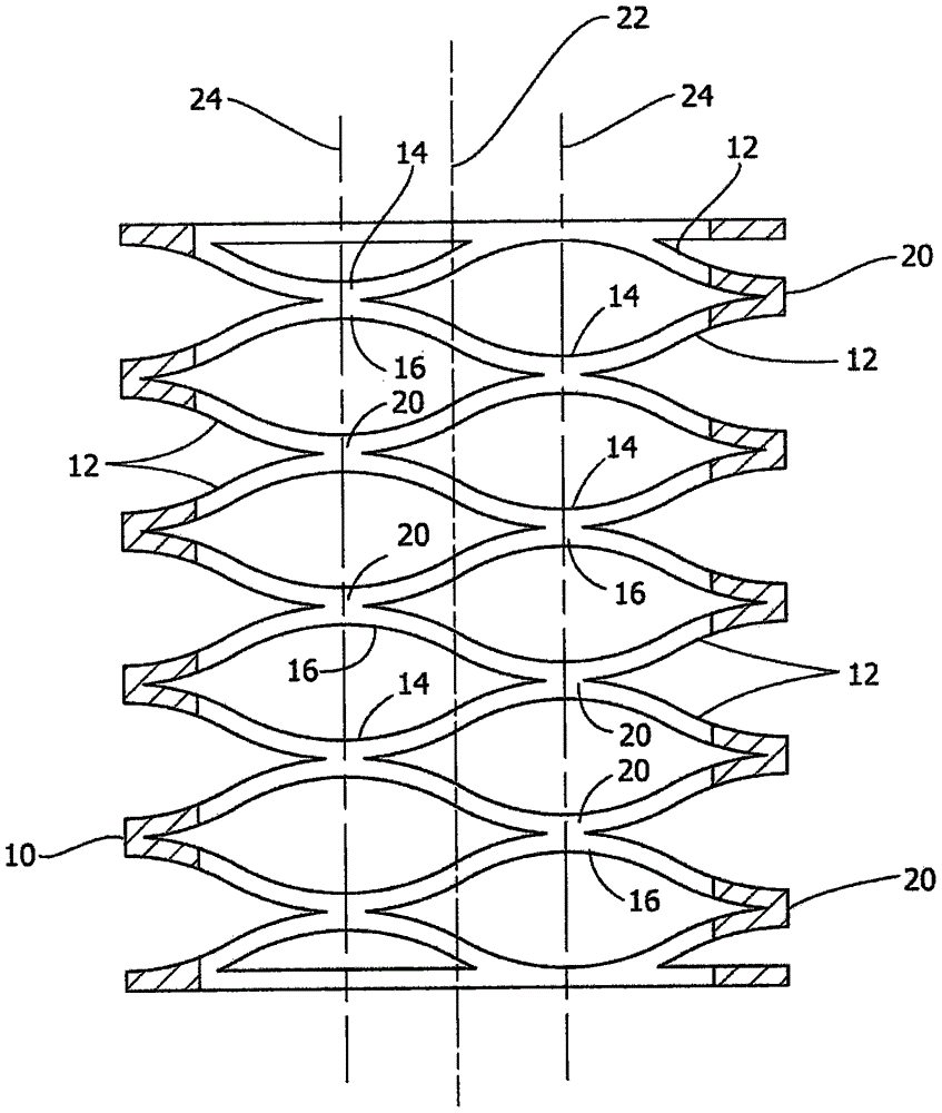
A bonded helical compression spring. The spring includes a plurality of layers having successive wave crests and troughs. First crests and first troughs of a first layer are aligned with respective second troughs and second crests of an adjacent second layer and with respective third troughs and third crests of an adjacent third layer. The first crests of the first layer are bonded to the second troughs of the adjacent second layer and the first troughs of the first layer are bonded to the third crests of the adjacent third layer. As the crests and troughs of adjacent layers are bonded together, friction between the crests and troughs is eliminated.

Description

technical field [0001] The present invention is directed to a compression spring with increased stiffness. In particular, the present invention is directed to a bonded compression spring that can be printed or molded in plastic. Background technique [0002] Due to their dynamic and mechanical properties, springs are widely used in many industries. For example, large springs are used in the automotive industry, or small springs are used in smaller electronic and / or mechanical devices. Steel springs are frequently used in view of their manufacturing quality, stiffness, strength and their ability to be mass produced. However, steel springs tend to be relatively heavy and their weight can be disadvantageous in certain applications. For example, in applications such as automobiles, airplanes, and train cars, it is critical to reduce the weight of different components to reduce the overall weight of the device. Other disadvantages of steel springs are that they have limited c...

Claims


Application Information

Patent Timeline
Patent Type & Authority Applications(China)
IPC IPC(8): F16F1/04F16F1/373B32B1/00
CPCF16F1/048F16F1/373F16F2226/00F16F2224/0233F16F1/328F16F3/0876F16F1/3732F16F2236/04
Inventor K·D·拉塞尔C·D·弗赖伊
Owner TE CONNECTIVITY CORP
Learn More