A device for long-term on-orbit storage of cryogenic liquid and cooling method thereof

A low-temperature liquid and low-temperature refrigerator technology, which is applied in the aerospace field, can solve problems such as endangering the safety of spacecraft astronauts, reducing the utilization rate of low-temperature liquid, and the danger of low-temperature liquid discharge, so as to reduce potential safety hazards, reduce operating load, The effect of improving the utilization rate

Active Publication Date: 2019-02-01
SHANGHAI AEROSPACE SYST ENG INST +1
View PDF7 Cites 3 Cited by
  • Summary
  • Abstract
  • Description
  • Claims
  • Application Information

AI Technical Summary

Problems solved by technology

However, due to regular exhaust, during the long-term on-orbit operation of the spacecraft, a large amount of cryogenic liquid will be lost, and the utilization rate of cryogenic liquid will be greatly reduced.
[0003] in addition, there are other potential hazards in the discharge of cryogenic liquids in the space environment
First, the microgravity environment makes the gas-liquid interface uncertain. If there is no gas-liquid separator, a large amount of liquid will be discharged during the exhaust process.
Secondly, the exhausted gas will diffuse around the spacecraft due to the influence of microgravity. If it is a flammable and explosive low-temperature propellant, it will seriously endanger the safety of the spacecraft and astronauts.
In addition, regular discharge makes the carrying amount of cryogenic liquid far greater than the rated liquid demand, which directly affects the quality of the storage tank, increases the operating load, and greatly increases the launch cost

Method used


Image

  • A device for long-term on-orbit storage of cryogenic liquid and cooling method thereof
  • A device for long-term on-orbit storage of cryogenic liquid and cooling method thereof
  • A device for long-term on-orbit storage of cryogenic liquid and cooling method thereof

Examples


Embodiment 1

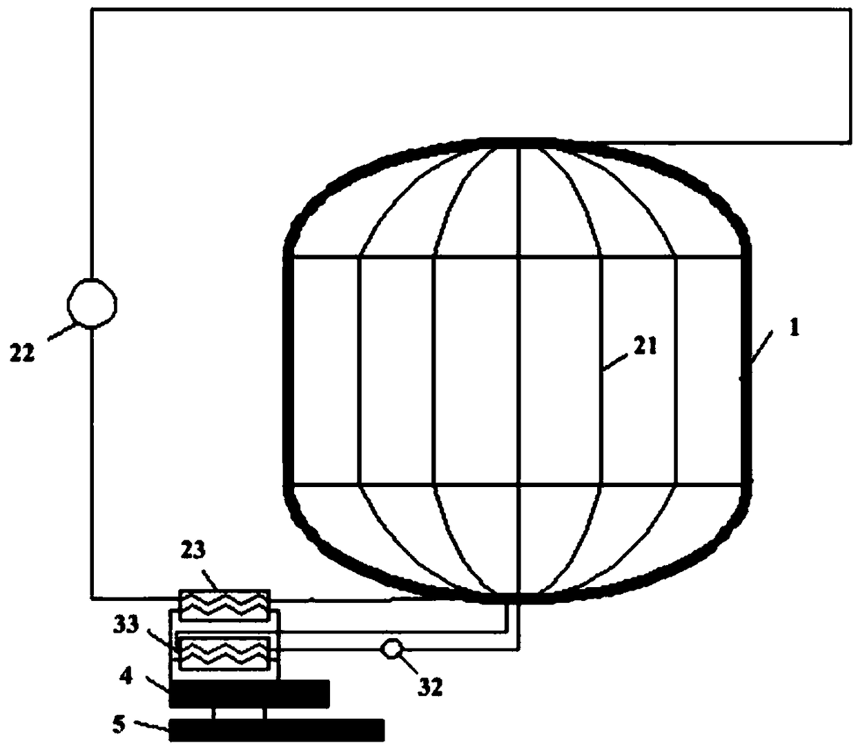
[0047] combine figure 1, the device for storing cryogenic liquid of the present invention is described in detail, and its structural schematic diagram is as follows figure 1 shown.

[0048] In this embodiment, the active thermal protection device outside the box includes: a cooling pipeline 21, a driving device 22, a first low-temperature refrigeration unit 23, and the cooling pipeline 21 is attached to the outer wall of the storage box 1. In this embodiment, the cooling pipeline includes multiple Roots are vertically pasted on the outer wall of the storage tank 1 at equal intervals. One end of the cooling pipeline 21 is connected to the driving device 22, the other end is connected to the first-stage low-temperature refrigeration unit 23, and the driving device 22 is connected to the first-stage low-temperature refrigeration unit 23. . The cooling pipeline 21, the driving device 22, and the first-stage low-temperature refrigeration unit 23 form a first circulation loop, and...

Embodiment 2

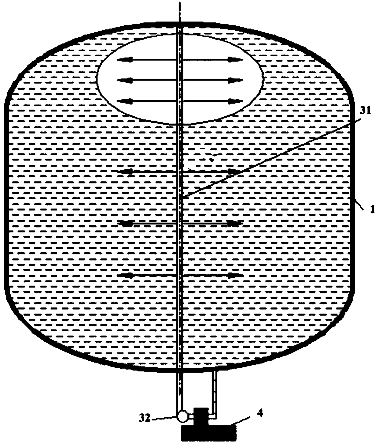
[0055] This embodiment is based on Embodiment 1, and the setting of the spray holes on the spray bar 31 has been improved. Nozzle holes, the nozzle holes are non-equidistant from top to bottom, and the number of holes becomes more and more sparse from top to bottom, its perspective view is as follows figure 2 As shown, the advantage of this setting is: because the position of the air pillow is usually above the storage tank, the arrangement of the nozzle holes allows more subcooled liquid to enter the air pillow and exchange heat with the gas phase, achieving a more effective and faster pressure control effect ; On the other hand, even if the nozzle holes in the lower part of the spray boom are sparsely arranged, it can still play a role in destroying the temperature stratification of liquid oxygen by mixing flow.

Embodiment 3

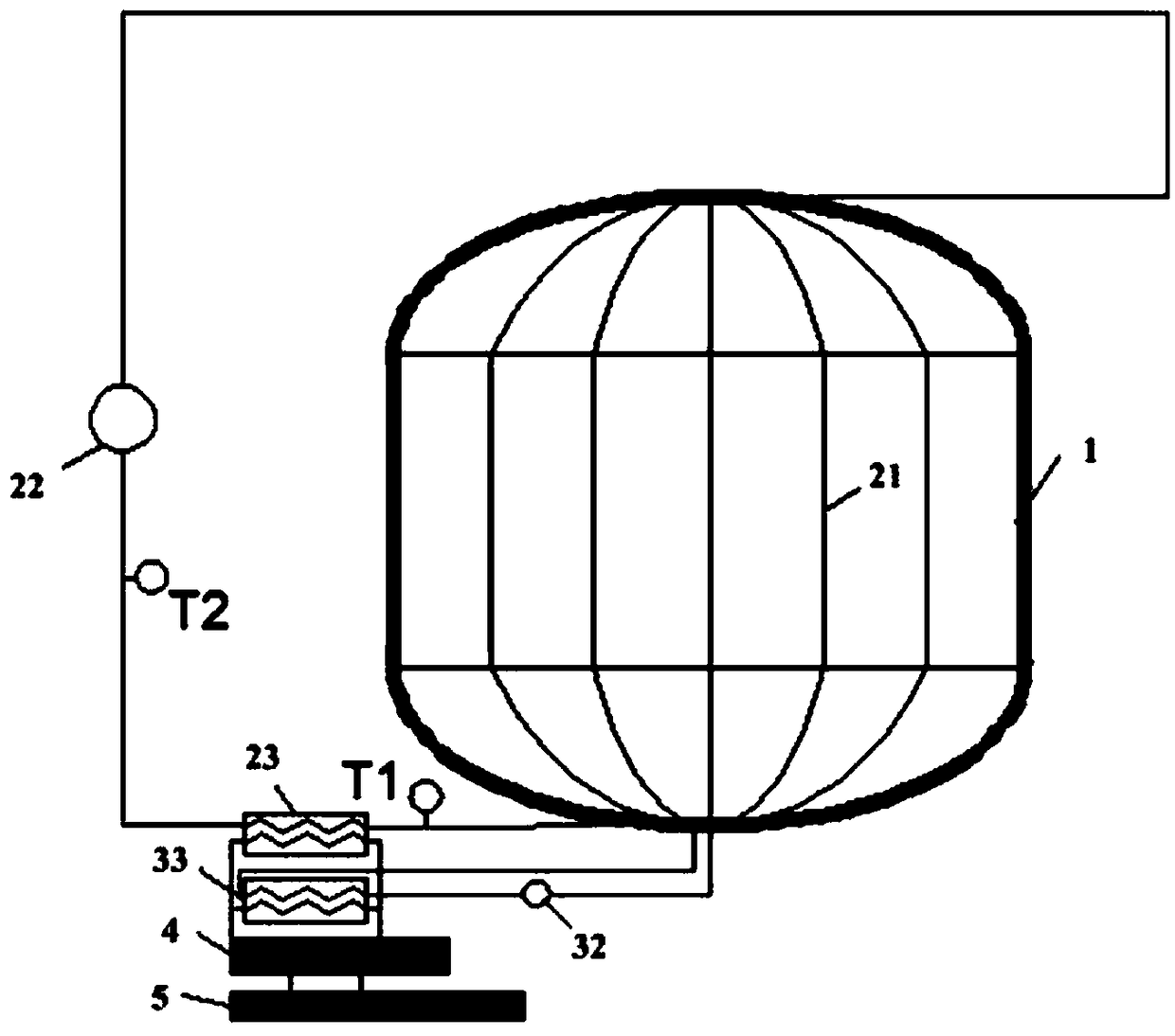
[0057] In this embodiment, a temperature sensor and a pressure sensor are added on the basis of embodiment 1 or embodiment 2 to control and monitor the operation of the system. The specific setting positions are as follows: image 3 As shown, a first temperature sensor T1 is provided between the cooling pipeline and the first-stage low-temperature refrigeration unit, and a second temperature sensor T2 is provided between the driving device and the first-stage low-temperature refrigeration unit.

[0058] In addition, a third temperature sensor T3 and a pressure sensor P are installed on the spray rod. When the pressure monitored by the pressure sensor P is greater than or equal to the preset threshold upper limit, that is, when the pressure in the storage tank 1 rises to the upper pressure limit of the storage tank 1 , the active cooling device in the tank is turned on to cool the low-temperature liquid in the tank and reduce the pressure in the storage tank 1, when the pressure...


PUM


Abstract

The invention discloses a device for storing low-temperature liquid in an orbit for a long time and a cooling method of the device. The device comprises a storage box, a box exterior initiative heat protection device and a box interior initiative cooling device. The storage box is used for storing the low-temperature liquid. The box exterior initiative heat protection device is arranged outside the storage box and used for cyclically cooling the outer wall of the storage box through a circulating medium. The box interior initiative cooling device is arranged in the storage box and used for cyclically cooling the low-temperature liquid in the storage box and controlling the pressure in the box. The method includes the steps that the circulating medium circulates in the box exterior initiative heat protection device arranged outside the storage box for cooling the outer side of the storage box; and the low-temperature liquid stored in the storage box circulates in the box interior initiative cooling device arranged in the storage box and is used for cooling low-temperature gas and the low-temperature liquid in the storage box and reducing the pressure in the box. The storage box is cooled in an interior and exterior double initiative manner, and therefore zero-evaporation storage of the low-temperature liquid in the orbit for a long time is achieved.

Description

technical field [0001] The invention relates to the field of aerospace technology, in particular to a device for long-term on-orbit storage of cryogenic liquid and a cooling method thereof. Background technique [0002] The low-temperature propellant long-term on-orbit storage technology can be applied to multiple aerospace fields such as upper stages, lunar exploration, deep space probes, and space fuel stations. Cryogenic propellants (such as the target liquid oxygen of the present invention) are characterized by a relatively low boiling point, although the development of thermal insulation technology can make the thermal insulation performance of cryogenic storage tanks reach a very high level, there will still be more or less evaporation , resulting in an increase in the pressure inside the tank. In order to ensure the safety of the cryogenic storage tank, when the pressure in the tank rises to a certain value, the traditional method is to control the pressure in the ta...

Claims


Application Information

Patent Timeline
Patent Type & Authority Patents(China)
IPC IPC(8): F17C1/00F17C13/00B64G1/40
CPCB64G1/402F17C1/00F17C13/00F17C2221/011F17C2270/0186
Inventor 耑锐王博杰王文何鹏赵栋梁张亮
Owner SHANGHAI AEROSPACE SYST ENG INST
Why Eureka
Try Eureka