LED lamp

A technology of LED lamps and lamp tubes, applied in the use of semiconductor lamps, adhesive types, shellac adhesives, etc., can solve the problems of unfavorable mass production, lower yield, sales discount, etc., and solve the problem that the output cannot be increased , Improve production efficiency, reduce the effect of time required

Active Publication Date: 2016-06-15
CHENHUI GUANGBAO TECH CO LTD
View PDF8 Cites 2 Cited by
  • Summary
  • Abstract
  • Description
  • Claims
  • Application Information

AI Technical Summary

Problems solved by technology

[0004] The disadvantages of this technology are as follows: first, since the driving power itself needs to occupy a large amount of space, it must be considered that the heat may damage the driving power when heating the cement; The cover must be of sufficient length
When the total length of the LED lamp is constant, it will inevitably reduce the effective area of ​​light emission, thereby reducing the lighting efficiency
Second, the cement in it is still the cement with traditional properties, that is, the curing temperature needs to reach above 180°C and the time is 2 minutes, so the heating efficiency is slow, which is not conducive to the large-scale production of the assembly line
Third, when the cement is heated above 180°C, it will inevitably cause some damage to the driving power supply, thereby reducing the yield
In addition, the power supply used in this application is a traditional power supply form (see Figure 16 ), which occupies a large space, based on the consideration of avoiding damage to the power supply and the need to block the power supply through the lamp cap, the length of the insulating tube is as long as about 50mm
[0006] The disadvantages of this technology are as follows: First, because it must use magnetically permeable metal parts to heat the solder paste, and the magnetically permeable metal parts are added between the lamp cap and the lamp tube as an additional component, and at the same time due to the connection between the lamp cap and the lamp tube The complex structure of the components greatly increases the production process and cost, which is not conducive to the industrial production of large-scale assembly lines
Since the hot-melt adhesive is located on the inner surface of the magnetically conductive metal part, even if a tight connection can be formed between the magnetically conductive metal part and the lamp tube after the hot-melt adhesive is cured, it is difficult to ensure the tightness between the magnetically conductive metal part and the lamp cap Connection, and the tight connection here can only completely depend on the tight fit between the magnetic metal parts and the size of the lamp head
This will place extremely high requirements on the dimensional accuracy of the lamp holder, magnetic metal parts and lamp tubes, which will greatly increase the production cost
Third, because the power supply 5 occupies a large space, it is not only susceptible to the influence of high-frequency heating and reduces the yield, but also makes the length of the lamp head relatively large, which affects the lighting effect of the LED lamp.
Fourth, from the perspective of industrial production and sales, if the insulating lamp holder used in this application cannot pass the UL certification, its sales in the market will be greatly reduced
Furthermore, the solidification temperature of solder paste in the prior art is generally 180-200° C., and the baking time is about 2 minutes. The problems brought about by it are that the heating efficiency is low and the production line is long.

Method used


Image

  • LED lamp
  • LED lamp
  • LED lamp

Examples


Embodiment 1

[0063]

Embodiment 2

[0065]

[0066]

Embodiment 3

[0068]

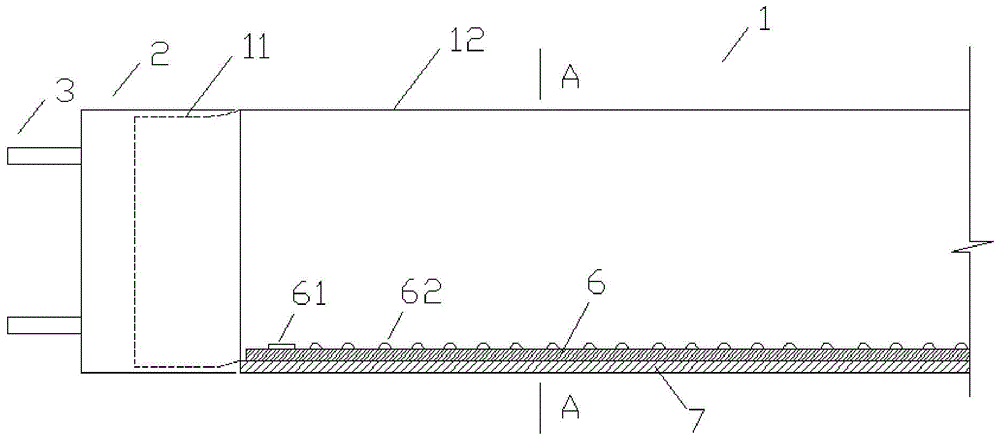
[0069] Preferably, the outer surface of the metal lamp cap 2 is flush with the outer surface of the straight portion 12 of the lamp tube 1 . The advantage of this arrangement is that, in the transportation and handling project, the entire LED lamp is uniformly stressed along its length, and stress concentration and damage will not occur due to the large diameter of the lamp cap or the large diameter of the lamp tube. In addition, this setting method will also make the LED lamp more beautiful as a whole. Wherein, the lamp tube 1 can be a plastic lamp tube or a glass lamp tube, or can be wrapped with a PPT plastic film on the inner or outer surface of the lamp tube, which can withstand a high temperature of 240°C. The material of the metal lamp cap 2 should be selected as a metal material capable of conducting heat to the welding mud through high-frequency heating equipment, and the welding mud is solidified and expanded by heating to achieve a tight connection betwe...


PUM

PropertyMeasurementUnit
heightaaaaaaaaaa
lengthaaaaaaaaaa
diameteraaaaaaaaaa

Abstract

The invention relates to an LED lamp. The LED lamp comprises a tube and a metal lamp holder capable of being used for high-frequency heating, wherein the tube comprises a straight part and necked parts arranged at two ends of the straight part, and smooth transition sections are arranged between the necked parts and the straight part; a lamp belt adheres to the straight part by the aid of an adhesive, and a patch power supply and LED light-emitting units are arranged on the lamp belt; the metal lamp holder is arranged outside the necked parts and is closely connected with the necked parts by the aid of welding mud; the metal lamp holder is 10-12 mm long, the necked parts are 6-8 mm long, and the gap between the metal lamp holder and the necked parts is 1-2 mm; the patch power supply is arranged in the position close to one end of the straight part, and the distance between the patch power supply and the end of the straight part is 3-5 mm. The LED lamp is simple in structure, high in lighting efficiency and low in rejection rate, comprises few components, is beneficial to industrial production line production and has unique technical advantages in aspects of breaking through the production bottleneck and substantially increasing the profit margin of products, and the welding mud is efficient and quick to solidify.

Description

technical field [0001] The invention relates to an LED lamp, which is suitable for the technical field of lighting engineering. Background technique [0002] For a long time, fluorescent lamps have been widely used in the field of lighting. The core components of fluorescent lamps are glass lamp tubes and filaments. The interior of the lamp tubes is coated with phosphor powder, and the filaments are coated with a layer of electron-emitting substances. The stem is used to fix the filament, and at the same time ensure that it is sealed with the glass lamp tube, and the tube is filled with inert gas and mercury vapor. The traditional fluorescent lamp manufacturing process includes: the production of glass lamp tubes, uniform coating of fluorescent powder in the inner cavity of the lamp tube, putting in the stem so that it can hold the filament, and coating the filament with electronic powder to make it enough to emit electrons. The substance, the stem and the tube body are bu...

Claims


Application Information

Patent Timeline
Patent Type & Authority Applications(China)
IPC IPC(8): F21K9/27F21K9/272F21K9/278F21K9/90F21V19/00F21V23/00H05B33/08C09J161/06C09J193/02C09J193/04C09J11/04F21Y115/10F21Y103/10H05B44/00
CPCF21K9/90F21V19/001F21V23/003C09J11/04C09J161/06C08L2205/03H05B45/00C08L93/02C08L93/04C08K2003/265C08K2003/327Y02B20/30
Inventor 赵国松郭朋鑫李信潮
Owner CHENHUI GUANGBAO TECH CO LTD
Why Eureka
Try Eureka