
An anti-corrosion ultra-high-voltage online hanging device and its application method

An ultra-high pressure, hanging piece technology, used in measuring devices, weather resistance/light resistance/corrosion resistance, instruments, etc., which can solve problems such as easy leakage, inability to open, and excessive torque.

Active Publication Date: 2018-10-02
西安华诺环境科技有限公司
View PDF9 Cites 0 Cited by
  • Summary
  • Abstract
  • Description
  • Claims
  • Application Information

AI Technical Summary

Problems solved by technology

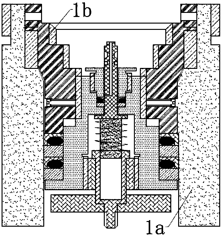
[0005] In order to overcome the above-mentioned defects of the prior art, the object of the present invention is to provide an anti-corrosion ultra-high voltage online hanging piece picking device and its use method, which can overcome the existing problems of the prior art such as high cost, low pressure resistance, easy leakage, weld seam Corrosion, chip hanger or device corrosion, excessive torque cannot be opened, valve opening and seal failure cannot be replaced, data loss, corrosion test point scrapped system corrosion cannot be tested, etc., to achieve online monitoring of medium corrosion in high-pressure or ultra-high pressure systems Non-stop production testing, providing technical support for the application of corrosion evaluation and corrosion control technology

Method used


Image

  • An anti-corrosion ultra-high-voltage online hanging device and its application method
  • An anti-corrosion ultra-high-voltage online hanging device and its application method
  • An anti-corrosion ultra-high-voltage online hanging device and its application method

Examples


Embodiment 1

[0165] 1. Production of the moving sealing rod 2b

[0166] 1.1. Design of 6R1 in moving sealing rod 2b

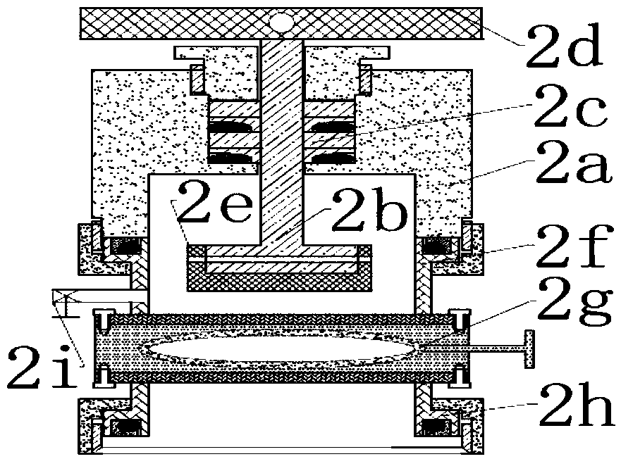
[0167] In the oilfield production system, the general pressure P 1 No more than 60MPa, according to manual operation requirements, working force F 1 Not exceeding 50kg, according to formula F 1 =3.14×(6R1) 2 ×P 1 ÷4 calculates the diameter of 6R1: 50=3.14×(6R1) 2 ×60÷4, 6R1=10.3m. Select 6R1=10.0mm.

[0168] 1.2 Design of other parameters of the moving sealing rod 2b

[0169] 6R2=φ28mm; 6R3=M8; 6R4=φ7.5; 6H1=7mm; 6H2=20mm; 6H3=489mm; 6H4=4mm; 6H5=15mm; 6H6=4mm.

[0170] 2. Manufacture of pressure relief sealing rod 4c

[0171] The design of each parameter in the pressure relief sealing rod 4c: 12R1=φ8mm; 12R2=φ1.5mm; 12R3=φ1.5mm; 12R4=φ14mm; 12H1=7.5mm; 12H2=28mm; 53mm; 12H6=1.5mm; 12H7=3mm; 12H8=7mm; 12H9=3mm; 12H10=10mm; 12H11=5mm; 12H13=24.5mm.

[0172] 3. Fabrication of the lower sealing nipple 4b

[0173] The design of various parameters in the lower sealin...

Embodiment 2

[0192] 1. Production of the moving sealing rod 2b

[0193] 1.1. Design of 6R1 in moving sealing rod 2b

[0194] When the pressure P 1 Up to 80MPa, according to manual operation requirements, working force F 1 Not exceeding 50kg, according to formula F 1 =3.14×(6R1) 2 ×P 1 ÷4 calculates the diameter of 6R1: 50=3.14×(6R1) 2 ×80÷4, 6R1=7.98mm. Select 6R1=8.0mm.

[0195] 1.2 Design of other parameters of the moving sealing rod 2b

[0196] 6R2=φ26mm; 6H1=6mm; other parameters are the same as example 1.

[0197] 2. Manufacture of pressure relief sealing rod 4c

[0198] The design of each parameter in the pressure relief sealing rod 4c: 12R1=φ6mm; 12R2=φ1mm; 12R4=φ12mm; 12H1=5.5mm; 12H11=4mm; other parameters are the same as example one.

[0199] 3. Fabrication of the lower sealing nipple 4b

[0200] The design of various parameters in the lower sealing nipple 4b: 11R1 = φ32-0.04mm; 11R2 = φ24.9mm; 11R3 = M16; 11R4 = φ6mm; 11R5 = φ11.4mm; 11R6 = M15.4; 11R7 = M23.4; 11R8=...

Embodiment 3

[0219] 1. Production of the moving sealing rod 2b

[0220] 1.1. Design of 6R1 in moving sealing rod 2b

[0221] When the pressure P 1 Up to 40MPa, according to manual operation requirements, working force F 1 Not exceeding 50kg, according to formula F 1 =3.14×(6R1) 2 ×P 1 ÷4 calculates the diameter of 6R1: 50=3.14×(6R1) 2 ×40÷4, 6R1=12.618mm. Select 6R1=12.0mm.

[0222] 1.2 Design of other parameters of the moving sealing rod 2b

[0223] 6R2=φ30mm; 6H1=9mm; other parameters are the same as example 1.

[0224] 2. Manufacture of pressure relief sealing rod 4c

[0225] The design of each parameter in the pressure relief sealing rod 4c: 12R1=φ10mm; Other parameters are the same as example one.

[0226] 3. Fabrication of the lower sealing nipple 4b

[0227] The design of various parameters in the lower sealing pup joint 4b: 11R1 = φ35-0.04mm; 11R2 = φ28.9mm; 11R4 = φ10mm; 11R5 = φ15.4mm; 11R6 = M19.4; 11R7 = M27.4; 11R8 = φ27; Other parameters are the same as example on...


PUM

PropertyMeasurementUnit
lengthaaaaaaaaaa
thicknessaaaaaaaaaa
thicknessaaaaaaaaaa

Abstract

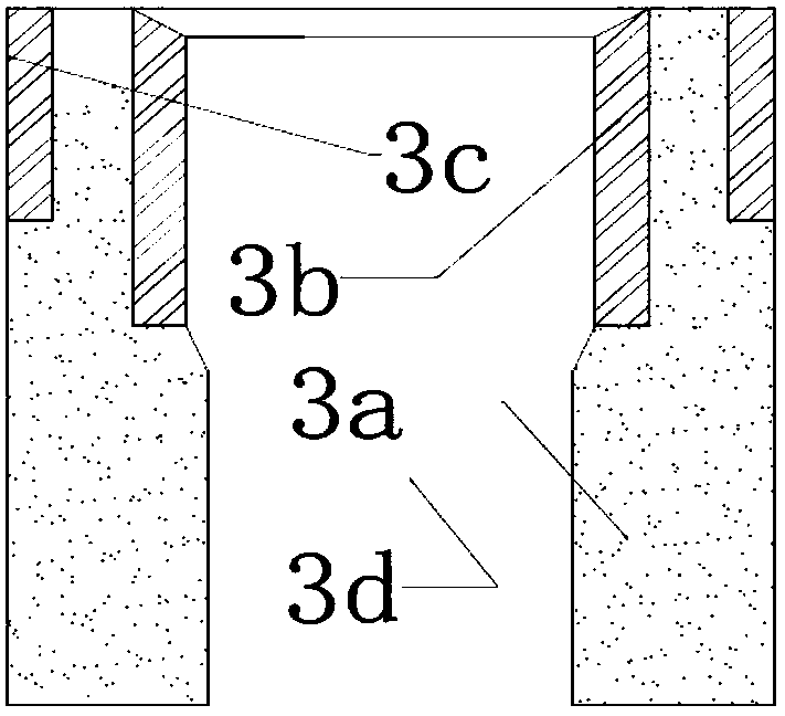
The invention discloses an anti-corrosion ultrahigh-pressure online piece hanging and taking device and a using method thereof.The anti-corrosion ultrahigh-pressure online piece hanging and taking device comprises a piece hanging device and a piece taking device.The piece hanging device comprises a welding nipple and a piece hanging sealing rod.A movable sealing rod is designed and installed in an upper hole in a sealing cavity of the piece taking device, an ultrahigh-pressure combined seal for rods is designed and installed around the upper hole in the sealing cavity and the movable sealing rod, a force application rod is installed at one outer end of the sealing cavity, the end, in the sealing cavity, of the movable sealing rod is connected with a piece taking head, the lower portion of the sealing cavity is connected with an upper connector, the upper connector is connected with a high-pressure ball valve, the high-pressure ball valve is connected with a lower connector, and a vent valve is installed on a connecting pipe of the upper connector.Due to the design of an anti-corrosion nipple in the piece hanging device, corrosion of the piece hanging device and a welding line can be effectively controlled, and thus the piece hanging device can be used for a long time.Due to the matching design of the movable sealing rod, the piece taking head, an upper sealing nipple and a pressure release sealing rod, the high-pressure ball valve can be replaced once leakage occurs, the piece hanging and taking device can be used for a long time, and the operating force in the piece hanging and taking process is small.

Description

technical field [0001] The invention relates to a device for online non-stop production hanging piece picking and hanging of media in a high-pressure container and a pipeline transportation system in operation, and in particular to an anti-corrosion ultra-high pressure online hanging piece picking device and a use method thereof. Background technique [0002] At present, there are many kinds of hanger or device for online non-stop production of pipelines on the market. Due to the defects of their structure and sealing, the following problems exist in the process of use: [0003] One is that the joints of the hanger or device are all O-rings. The sealing pressure of the O-rings is generally lower than 20MPa, which cannot be adapted to gas-liquid high-pressure containers and gas-liquid under high-pressure or ultra-high pressure conditions. The on-line non-stop corrosion test of the pipeline transportation system, and the O-ring is prone to seal failure during use, resulting in...

Claims


Application Information

Patent Timeline
Patent Type & Authority Patents(China)
IPC IPC(8): G01N17/00
CPCG01N17/00
Inventor 杜素珍毕刚周生杰郭学辉郭潇
Owner 西安华诺环境科技有限公司
Learn More