
A State Observer Based Predictive Control Method for Combined Cooling, Heating and Power System

A technology of combined cooling, heating and power supply and a state observer, which is applied in the direction of adaptive control, general control system, control/regulation system, etc., can solve the problem of measurement noise controller interference, difficult design of control strategy, large inertia of the joint supply system and Delay and other problems, to achieve the effect of suppressing the impact, improving the quality of dynamic adjustment, and ensuring the quality of control

Active Publication Date: 2018-04-24
SOUTHEAST UNIV
View PDF4 Cites 0 Cited by
  • Summary
  • Abstract
  • Description
  • Claims
  • Application Information

AI Technical Summary

Problems solved by technology

[0003] Scholars at home and abroad have done a lot of research work on the operation optimization and modeling of the cogeneration system, but the research on the control strategy is insufficient.
Furthermore, due to the large inertia and delay of the cogeneration system, it is difficult to design the control strategy
The joint supply system also has nonlinear characteristics of valves and other equipment and coupling characteristics of upstream and downstream loops, which makes it difficult for traditional control methods to achieve satisfactory control effects
At the same time, it is difficult to obtain good control quality due to disturbance, measurement noise, and uncertainty that have a certain interference effect on the controller.
The conventional PID control scheme commonly used at present is difficult to effectively deal with the large delay and strong coupling characteristics of the controlled object

Method used


Image

  • A State Observer Based Predictive Control Method for Combined Cooling, Heating and Power System
  • A State Observer Based Predictive Control Method for Combined Cooling, Heating and Power System
  • A State Observer Based Predictive Control Method for Combined Cooling, Heating and Power System

Examples


Embodiment Construction

[0056] The technical solution of the present invention will be further introduced below in combination with specific embodiments.

[0057] The invention discloses a predictive control method for a combined cooling, heating and power supply system based on a state observer. The system block diagram is as follows figure 1 Shown, the inventive method comprises the following steps:

[0058]S1: Obtain the step response model of the micro gas turbine combined cooling, heating and power supply object. The dynamic characteristics of the CCHP system can be described by the transfer function model shown in formula (1):

[0059]

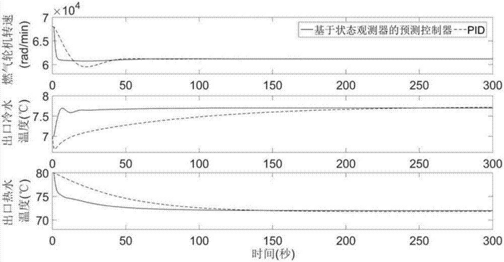
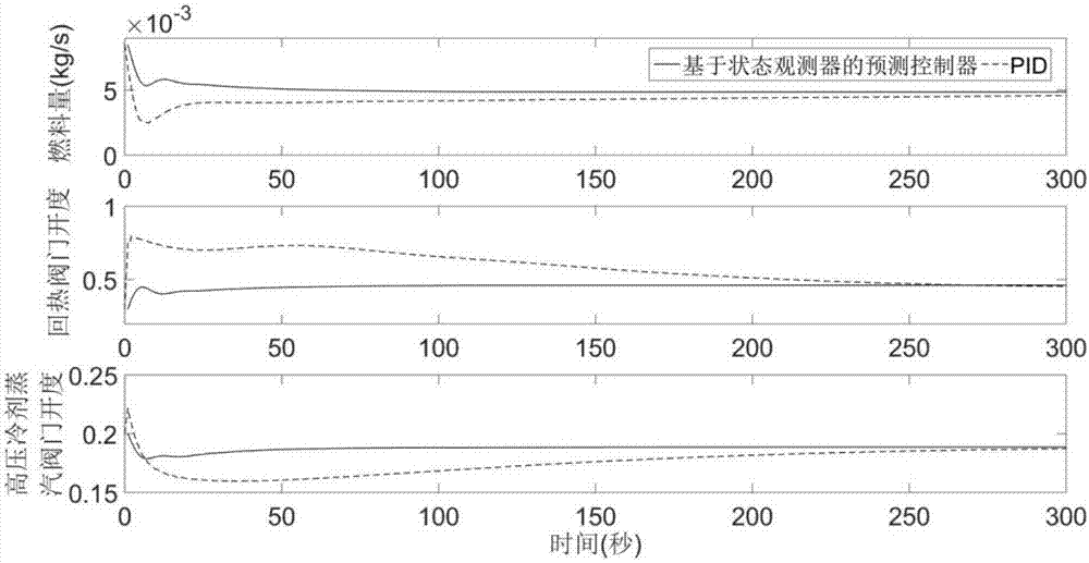
[0060] In formula (1), u 1 , u 2 , u 3 Respectively represent the amount of fuel (kg / s), the opening of the reheating valve and the opening of the high-pressure refrigerant steam valve; y 1 、y 2 、y 3 Respectively represent gas turbine speed (rad / min), outlet cold water temperature (°C) and outlet hot water temperature (°C). The transfer functions are...


PUM


Abstract

The invention discloses a combined cooling heating and power supply system prediction control method based on a state observer. The combined cooling heating and power supply system prediction control method comprises the steps of: S1, acquiring a step response model of a miniature gas turbine combined cooling heating and power supply object; S2, determining a state-space model of the combined supply object; S3, setting parameters of the controller, and predicting a future state of the combined supply system; S4, initializing the controller; S5, calculating deviations; S6, correcting state quantity online; S7, predicting future output; S8, calculating an optimal control increment for fuel quantity, a backheating valve opening degree and a high-pressure refrigerant steam valve opening degree at the next moment; S9, calculating an optimal control quantity for fuel quantity, a backheating valve opening degree and a high-pressure refrigerant steam valve opening degree at the next moment; S10, outputting the optimal control quantity, and calculating and updating an output prediction value at the next moment according to measurement signals; and carrying out the steps S5-S10 repeatedly in each sampling period. The combined cooling heating and power supply system prediction control method can improve the control quality.

Description

technical field [0001] The invention relates to the field of thermal automatic control, in particular to a state observer-based predictive control method for a combined cooling, heating and power supply system. Background technique [0002] Cogeneration of cooling, heating and power is an important plan and measure to realize cascade utilization of energy and improve the utilization rate of primary energy. The combined cooling, heating and power system powered by micro gas turbines has gradually become one of the development trends of current world energy technology due to its advantages of high energy utilization efficiency, low emission, distributed, safety and easy adjustment. [0003] Scholars at home and abroad have done a lot of research work on the operation optimization and modeling of the cogeneration system, but the research on the control strategy is insufficient. Furthermore, due to the large inertia and delay of the cogeneration system, it is difficult to desig...

Claims


Application Information

Patent Timeline
Patent Type & Authority Patents(China)
IPC IPC(8): G05B13/04
CPCG05B13/042
Inventor 廖霈之李益国沈炯刘西陲吴啸
Owner SOUTHEAST UNIV
Learn More