Method for generating multiple orbital angular momentum beams

A technology of orbital angular momentum and multi-beam, which is applied to antennas, electrical components, and radiation element structures, can solve the problems of small coverage, complex structure, and single mode, and achieve low cost, high radiation efficiency, and low loss. Effect

Active Publication Date: 2016-06-15
XIDIAN UNIV
View PDF5 Cites 36 Cited by
  • Summary
  • Abstract
  • Description
  • Claims
  • Application Information

AI Technical Summary

Problems solved by technology

[0004] The purpose of the present invention is to propose a multi-beam generation method for orbital angular momentum to solve the above-mentioned deficiencies of

Method used


Image

  • Method for generating multiple orbital angular momentum beams
  • Method for generating multiple orbital angular momentum beams
  • Method for generating multiple orbital angular momentum beams

Examples


Embodiment 1

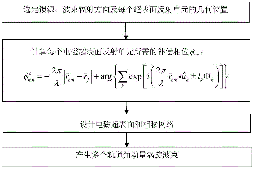
[0041] Embodiment 1: Generate orbital angular momentum vortex beams with radiation mode numbers of 1 in different directions.

[0042] Step 1, select the geometric positional relationship.

[0043] 1a) Set parameters:

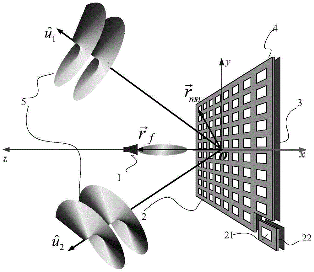
[0044] refer to figure 2 , take the relative position of the center of horn 1 antenna m, that is, 0 on the x-axis, 0 on the y-axis, and 0.4 meters on the z-axis; two angular momentum beams are set to be generated, and the radiation direction of the first angular momentum beam is set as The radiation direction of the second angular momentum beam is set as The total number of rows M=20 of the electromagnetic metasurface reflection unit, the total number of columns N=20, the distance between the centers of two adjacent electromagnetic metasurface reflection units D=25 millimeters, the size of the dielectric substrate 22 is 0.5 × 0.5 × 0.001 meters, the electromagnetic metasurface The size of the surface reflection unit 21 is 25×25 mm; the distance d betw...

Embodiment 2

[0062] Embodiment 2: Generate orbital angular momentum vortex beams with 2 radiation modes in different directions.

[0063] Step 1, select the geometric positional relationship.

[0064] Referring to Embodiment 1, the geometric positional relationship consistent with Embodiment 1 is selected.

[0065] Step 2, calculate the compensation phase required for each electromagnetic metasurface reflection unit

[0066] 2.1) Given that the operating frequency f of the horn antenna is 5.8GHz, take the eigenmode number l of the first angular momentum beam 1 = 2, the eigenmode number l of the second angular momentum beam 2 =2, calculate the required compensation phase of each electromagnetic metasurface reflection unit with reference to the method given in Embodiment 1

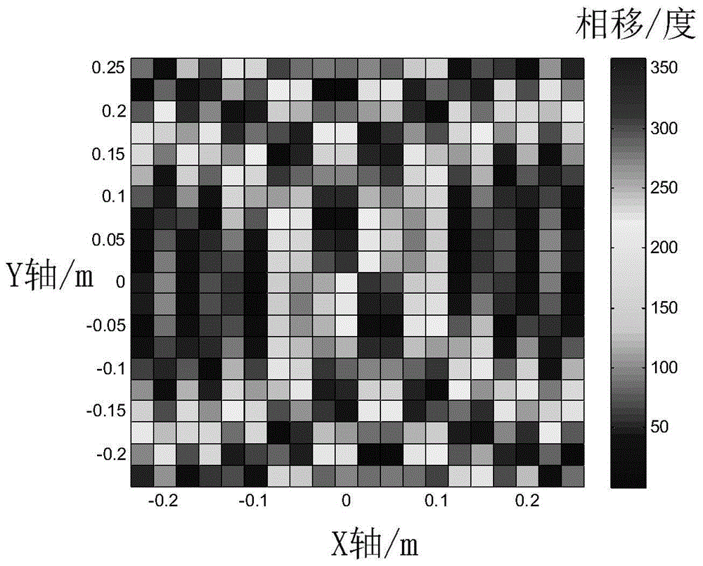
[0067] 2.2) Compensate the phase according to the calculated mth row and nth column The value of , draw the phase distribution map of all electromagnetic metasurface reflection units, such as Figure 7 as shown...

Embodiment 3

[0076] Embodiment 3: Generate orbital angular momentum vortex beams with radiation mode numbers of 1 and 2 in different directions.

[0077] Step A, select the geometric positional relationship.

[0078] Referring to Embodiment 1, the geometric positional relationship consistent with Embodiment 1 is selected.

[0079] Step B, calculate the compensation phase required for each electromagnetic metasurface reflection unit

[0080] B1) Given that the operating frequency f of the horn antenna is 5.8GHz, take the eigenmode number l of the first angular momentum beam 1 = 1, the eigenmode number l of the second angular momentum beam 2 =2, calculate the required compensation phase of each electromagnetic metasurface reflection unit with reference to the method given in Embodiment 1

[0081] B2) Compensate the phase according to the calculated mth row and nth column The value of , draw the phase distribution map of all electromagnetic metasurface reflection units, such as Fig...


PUM


Abstract

The invention discloses a method for generating multiple orbital angular momentum beams, and mainly aims at solving the problems that multiple orbital angular momentum vortex beams which radiate towards different directions and are the same or different in mode number cannot be simultaneously generated under a single working frequency in the prior art. According to the implementation scheme, the method comprises the following steps: selecting a feed source, a wave beam radiation direction and a geometric position of each reflecting unit; calculating a compensation phase matrix required by each super-surface reflecting unit according to the geometric position, the working frequency and the required orbital angular momentum mode; selecting electromagnetic super-surface units with different sizes to design a phase-shift network; putting the feed source at the central axial position of the electromagnetic super-surface and making an incident wave sent out from the feed source radiate the electromagnetic super-surface to obtain a compensation phase provided by the phase-shift network; and generating multiple orbital angular momentum vortex beams with vortex wavefronts in the set direction. The method can effectively improve the capacity and the coverage area of an orbital angular momentum wireless communication system and is used for modulating and multiplexing different signals in the wireless communication system.

Description

technical field [0001] The invention belongs to the technical field of wireless communication, in particular to a method for generating an orbital angular momentum electromagnetic vortex field, which can be used in radio frequency and microwave bands. Background technique [0002] Orbital angular momentum vortex waves have been widely studied and applied in recent years, but the research and application in the fields of radio frequency and wireless communication are relatively lagging behind. Until 2007, B.Thide in Sweden successfully applied it to the field of radio frequency wireless communication by using the method of generating orbital angular momentum OAM by using an array antenna, so the application of OAM electromagnetic vortex field in wireless communication has gradually become a research hotspot today. . So far, the main methods used to generate OAM beams are transmission rotating phase plates, helical paraboloids and array antennas. [0003] Among these schemes...

Claims


Application Information

Patent Timeline
IPC IPC(8): H01Q1/36H01Q3/26
CPCH01Q1/36H01Q3/2605
Inventor 李龙余世星石光明刘海霞朱诚史琰周潇潇
Owner XIDIAN UNIV
Why Eureka
Try Eureka