

Preparation and application of reflecting type fluorescent glass light conversion assembly
A fluorescent glass and light conversion technology is applied in the field of preparation of reflective fluorescent glass light conversion components to achieve high reflection, improve extraction efficiency, and solve the effects of luminous loss
- Summary
- Abstract
- Description
- Claims
- Application Information
AI Technical Summary
Problems solved by technology
Method used
Image

Examples
Embodiment 1
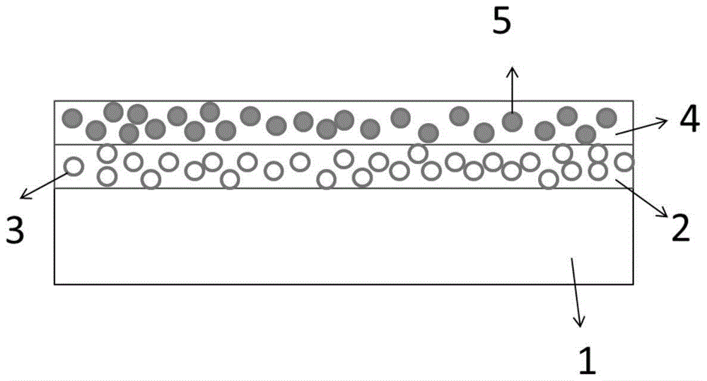
[0035] Example 1. With figure 1 The manufacturing method of the reflective fluorescent glass light conversion component is described in detail.
[0036]Glass substrate A is ordinary soda-lime glass with a thickness of 0.5 mm, and its refractive index at a wavelength of 460 nm is about 1.52. The glass transition temperature is 570°C, and the softening temperature is 620°C;
[0037] Glass B is a low-melting phosphate glass whose components contain P 2 o 5 : 41%, ZnO: 34%, B 2 o 3 : 19%, (Li 2 O3%+Na 2 O1.5%+K 2 (01.5%): 6%. The glass has a refractive index of about 1.49 at a wavelength of 460 nanometers, a glass transition temperature of 480°C, and a softening temperature of 526°C;
[0038] Reflector 3 is BaSO 4 , its particle size distribution d 50 is 50 microns;
[0039] Phosphor 5 is YAG yellow-green phosphor, and its particle size distribution is d 50 is 12 microns.
[0040] Mix 20 g of Glass B powder with BaSO 4 Add 10 grams of powder to 4 grams of organic li...
Embodiment 2
[0047] The difference between embodiment 2 and embodiment 1 is that the phosphor 5 is a mixture of green phosphor powder and red phosphor powder.
Embodiment 3
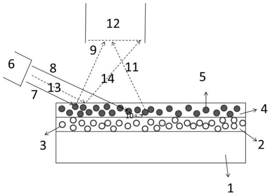
[0048] Example 3. With figure 2 Example 3 will be described in detail.
[0049] The blue laser light source array 6 emits blue light 7 and 8, excites the green phosphor particles in the fluorescent glass coating 4, emits green light 9, and is collected by the optomechanical system 12; the blue light 8 excites the green phosphor particles in the fluorescent glass coating 4 The red phosphor particles emit red light 10, the red light 10 is reflected at the interface between the fluorescent glass coating and the reflector glass coating, and finally emerges as light 11 and is collected by the optical-mechanical system 12; the blue light 13 is incident on the fluorescent glass coating The interface between layer 4 and air is reflected, and light 14 is collected by optomechanical system 12 .
PUM
| Property | Measurement | Unit |
|---|---|---|
| Thickness | aaaaa | aaaaa |
| Glass transition temperature | aaaaa | aaaaa |
| Softening temperature | aaaaa | aaaaa |
Abstract
Description
Claims
Application Information