Method of removing metal artifact from CT image

A technology for metal artifacts and CT images, which is applied in image enhancement, image analysis, image data processing, etc., can solve the problems of large amount of computation, increase the influence of metal artifacts, and large amount of projection data, so as to achieve the removal of metal artifacts , Contribute to the effect of accurate judgment of the disease

Active Publication Date: 2016-06-22
SAINUO WEISHENG SCI & TECH BEIJING
View PDF5 Cites 20 Cited by
  • Summary
  • Abstract
  • Description
  • Claims
  • Application Information

AI Technical Summary

Problems solved by technology

[0006] 1) Because there is a very strong magnetic field in the MRI machine and MRI examination room, those who have cardiac pacemakers, and those who have left metal clips and metal stents after vascular surgery, or other coronary arteries, esophagus, and prostate 1. It is strictly forbidden to undergo MRI examination for patients undergoing metal stent surgery in the biliary tract. Otherwise, due to the metal being attracted by a strong magnetic field and moving, serious consequences may even be life-threatening.
[0007] 2) For patients with metal implants, a large number of artifacts may appear on the metal implant area of ​​the MRI image during inspection, which affects the image diagnostic performance
[0012] The iterative reconstruction algorithm is theoretically a very good method for removing metal artifacts. This algorithm can effectively remove metal artifacts and suppress noise, and can well present the structure of metal objects. Practical
Removing metal artifacts in the projection domain is a pre-processing method and has certain advantages, because the post-processing method of removing metal artifacts in the image domain needs to go through back-projection algorithms such as FBP, which will increase the impact of me

Method used


Image

  • Method of removing metal artifact from CT image
  • Method of removing metal artifact from CT image
  • Method of removing metal artifact from CT image

Examples


Embodiment Construction

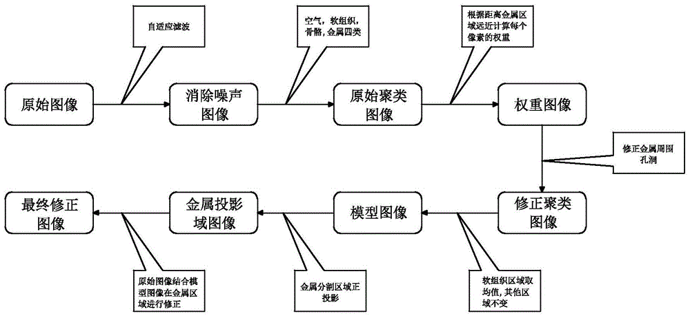
[0051] see figure 1 , a method for removing metal artifacts from CT images, the step of removing metal artifacts comprises:

[0052] A. Image preprocessing: use the adaptive filtering method to remove noise and some streak artifacts in the CT image to obtain the original reconstructed image; the present invention uses median filtering to eliminate part of the noise, and more complex filtering methods can be used in principle to better eliminate noise.

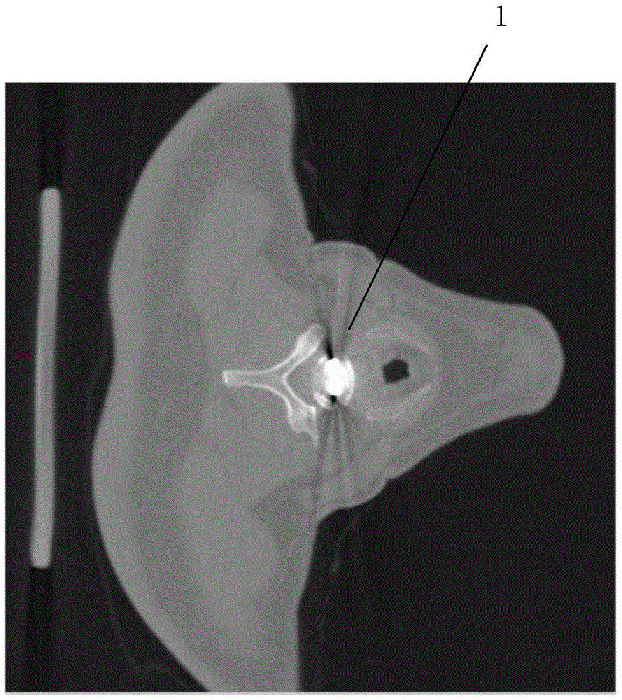
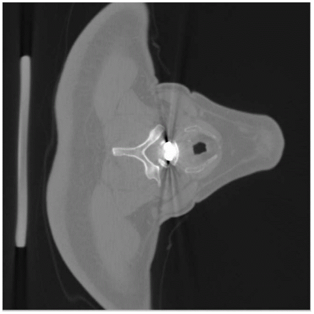
[0053] figure 2 It is the original CT image, and the original CT image is the CT reconstructed image that has not been processed to eliminate metal artifacts. It can basically be equivalent to the image in the traditional sense, but the format may be somewhat different (dicom, etc.). image 3 It is the image after adaptive filtering (because the noise of the original image is very small, the difference between the preprocessed image and the original image is not obvious).

[0054] B. Image segmentation: using a clustering s...


PUM


Abstract

The present invention relates to a method of removing metal artifact from a CT image. The method comprises the steps of firstly carrying out the pre-processing via the image adaptive filtering to obtain an original reconstruction image from which the noise and a part of streak artifact are removed; then segmenting the original reconstruction image via a clustering method to obtain the areas of different tissues, establishing a model image, at the same time, carrying out the orthographic projection on a segmented metal area to obtain the position of the metal area in a projection domain; and then carrying out the orthographic projection on the model image to obtain the projection data of the model image, and then using the projection domain data of the model image to substitute for the projection domain data of the original reconstruction image according to the previously obtained position of the metal area in the projection domain; finally carrying out the filtering back projection on the repaired projection domain data to obtain a final corrected image. The method of the present invention reduces a real image accurately, enables the metal artifact to be removed effectively, and helps doctors to judge the states of illnesses accurately.

Description

technical field [0001] The invention relates to enhancement or restoration of CT images, in particular to a method for removing metal artifacts from CT images. Background technique [0002] Medically, metal implants have been used to repair the human body for more than 400 years. In the early days, doctors used pure gold plates to repair skulls and inlays, and then used silver, iron, and iron-based alloys to fix fractures. Joints, cobalt-based alloys were used as human implants in modern times, and stainless steel was also used in large quantities. With the development of the rare metal industry, rare metals such as processed titanium, cast titanium, and niobium were clinically applied to the human body. Today, titanium alloys Because of its high strength, good corrosion resistance, and high heat resistance, it is the first choice for human implants and has been widely used. [0003] MRI is a biological magnetic spin imaging technology. It utilizes the characteristics of nu...

Claims


Application Information

Patent Timeline
IPC IPC(8): G06T5/00
CPCG06T5/005G06T2207/10081G06T2207/30008
Inventor 李宇寂任毅
Owner SAINUO WEISHENG SCI & TECH BEIJING
Why Eureka
Try Eureka