Pulse injection-based three-phase switched reluctance motor position sensorless control method

A three-phase switching, pulse injection technology, applied in motor control, motor generator control, electronic commutation motor control and other directions, can solve the problems of large amount of calculation, poor robustness, poor portability, etc., to achieve reliability and accuracy High, easy real-time control, reduced computational cost

Inactive Publication Date: 2016-06-22
XIAMEN UNIV OF TECH
View PDF2 Cites 14 Cited by
  • Summary
  • Abstract
  • Description
  • Claims
  • Application Information

AI Technical Summary

Problems solved by technology

APositionSensorlessControlSystemofSRMoverWideSpeedRange.The7thInternationalConferenceonPowerElectronics: 640~643 adopts the current flux linkage method. The basic idea is that according to the salient polarity effect of the motor, different rotor positions correspond to different flux linkage-current curves, and the reference flux linkage is obtained through the current look-up table. However, this method Requires a large amount of table lookup data, poor portability
RotorpositionobserverforsensorlesscontrolofSRM, XIXSymposiumElectromagneticPhenomenainNonlinearCircuits, Maribor, Slovenia, 28-30june2006, pp.161~162 uses the Luenberger observer to calculate the rotor angle through the current and voltage signals in the operation of the switched reluctance motor. This method has a relatively large amount of calculation, and the observer linear model Sensitive to parameters, poor robustness
ANNbasedsensorlessrotorpositionestimationfortheSwitchedReluctanceMotor[C].NirmaUniversityInternationalEngineering(NUiCONE), 2011:1-6 adopts the neural network intelligent control method, which can approach any nonlinear rational function in theory, but requires a large number of training samples, and there is still a big gap from the actual application

Method used


Image

  • Pulse injection-based three-phase switched reluctance motor position sensorless control method
  • Pulse injection-based three-phase switched reluctance motor position sensorless control method
  • Pulse injection-based three-phase switched reluctance motor position sensorless control method

Examples


Embodiment Construction

[0030] The present invention will be further described in conjunction with the accompanying drawings and specific embodiments.

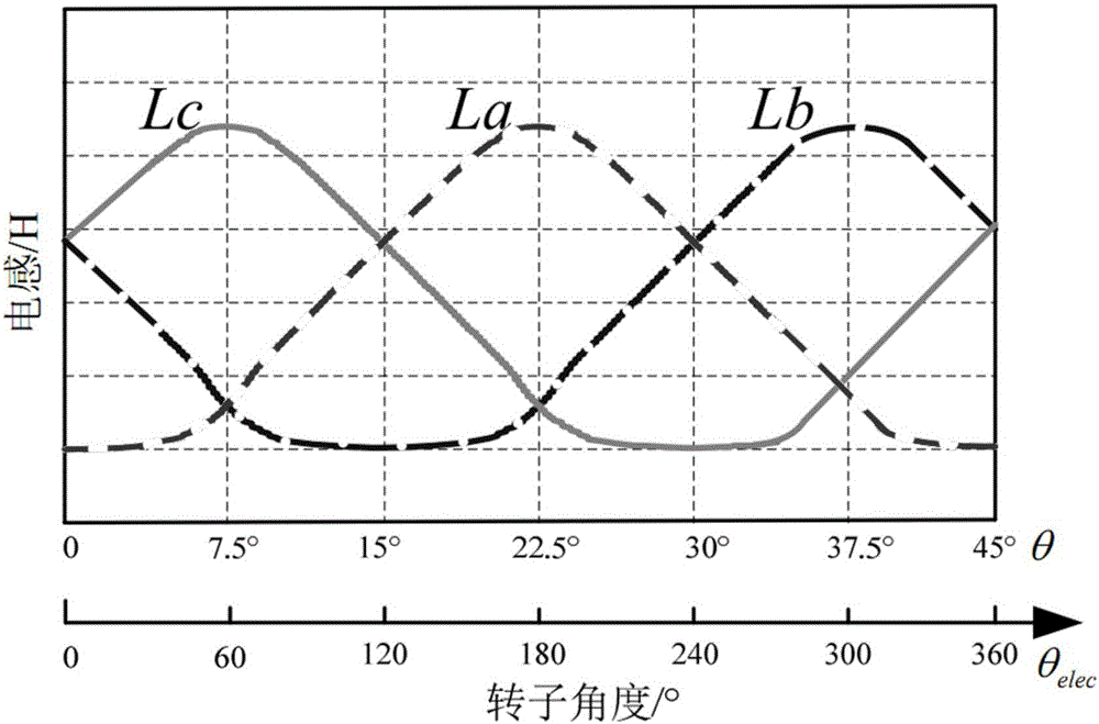
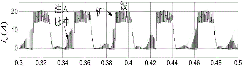
[0031] The three-phase switched reluctance motor position sensorless control method based on pulse injection injects pulses into the non-conducting phase of the switched reluctance motor, performs current chopping control on the conducting phase, and then measures the phase current of each phase to calculate The current slope difference of each phase, and then the three-phase equivalent inductance is obtained through the current slope difference, and the inductance vector is synthesized. Finally, the rotor position angle θ is estimated through the inductance vector, and then the rotor speed is calculated. The invention is suitable for the control of three-phase switched reluctance motors. The present invention will be further described in detail below by taking a three-phase (respectively named a-phase, b-phase and c-phase) 12 / 8 structured switched r...


PUM


Abstract

The invention relates to the technical field of position sensorless control of switched reluctance motors, in particular to a position sensorless control method for three-phase switched reluctance motors based on pulse injection. The invention proposes a three-phase switched reluctance motor position sensorless control method based on pulse injection, which is suitable for the control of three-phase switched reluctance motors. Phase chopper control is performed, the phase current is detected by the current sensor, and the current slope difference is calculated. Then, the three-phase equivalent inductance is obtained according to the current slope difference, and the inductance vector is synthesized. Finally, the rotor position information is extracted from the inductance vector to obtain the rotor speed. The invention has the advantages of simple structure and easy realization, greatly reduced calculation amount, and high reliability and precision.

Description

technical field [0001] The invention belongs to the technical field of position sensorless control of switched reluctance motors, and in particular relates to a position sensorless control method for three-phase switched reluctance motors based on pulse injection with simple structure, high reliability and high precision. Background technique [0002] Switched reluctance motor (Switched Reluctance Motor, SRM), also known as "reluctance motor", has a simple structure, flexible control, simple power converter, reliable operation, and has broad application prospects. For the switched reluctance motor drive system (SwitchedReluctanceMotorDrives, SRD), accurate rotor position is a necessary condition for the stable operation of the motor. For some industrial applications with harsh environments, such as coal mining machines, the detection accuracy and reliability of traditional position sensors are seriously affected. In recent years, the development of sensorless control system...

Claims


Application Information

Patent Timeline
Patent Type & Authority Applications(China)
IPC IPC(8): H02P21/18H02P21/24
CPCH02P2203/01
Inventor 张辑陈丽安魏荣宗陈天翔彭彦卿郑雪钦
Owner XIAMEN UNIV OF TECH
Why Eureka
Try Eureka