Volatile organic waste gas treatment process and treatment equipment used in treatment process
A volatile organic waste gas treatment equipment technology, applied in the field of volatile organic waste gas treatment process and its treatment equipment, can solve the problems of incomplete adsorption, increase of production cost of enterprises, increase of operating cost, etc., to save energy and reduce harmful substances The effect of low content and running cost
- Summary
- Abstract
- Description
- Claims
- Application Information
AI Technical Summary
Problems solved by technology
Method used
Image

Examples
specific Embodiment approach
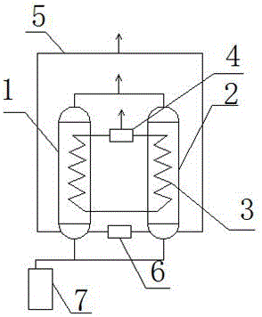
[0018] figure 1 A specific embodiment of the present invention is shown: a treatment equipment for volatile organic waste gas, wherein the treatment equipment includes a first processor 1, a second processor 2, an exhaust gas inlet pipe, an exhaust gas outlet pipe, a nitrogen circulation pipe 3, Gasifier 4, collection tank 7 and exhaust pipe blower 6, said nitrogen circulation pipeline 3 is at least partly located inside said first processor 1 and said second processor 2, said not placed in said first processor The nitrogen circulation pipeline 3 inside the device 1 and the second processor 2 is connected with an air inlet and an air outlet, and a vaporizer 4 is installed on the gas outlet, and the first processor 1 and the second processor The lower end of the processor 2 is provided with an exhaust gas inlet pipe, and the exhaust gas inlet pipe is connected with an exhaust gas blower 6, and the upper ends of the first processor 1 and the second processor 2 are provided with ...
Embodiment 1
[0022] The organic waste gas is passed into the inside of the first processor and the second processor through the exhaust gas blower from the exhaust gas inlet pipe (passing speed is 30cm 3 / min), injecting cryogenic nitrogen gas (with a temperature of -180°C) into the nitrogen circulation pipeline, and the cryogenic nitrogen gas is mixed with the cryogenic nitrogen gas inside the first processor and the second processor Heat exchange, when the temperature of the organic waste gas drops below the freezing point, organic waste is formed and adheres to the inner walls of the first processor and the second processor, and the cryogenic nitrogen gas after heat exchange is discharged from the gas outlet, and the heat After the exchange, turn on the hot air blowing device for 0.5h, heat, and raise the temperature of the organic waste to above the melting point, and flow it into the collection pool.
Embodiment 2
[0024] The organic waste gas is passed into the inside of the first processor and the second processor through the exhaust gas blower from the exhaust gas inlet pipe (passing speed is 50cm 3 / min), injecting cryogenic nitrogen gas (with a temperature of -150°C) into the nitrogen circulation pipeline, and the cryogenic nitrogen gas is mixed with the cryogenic nitrogen gas inside the first processor and the second processor Heat exchange, when the temperature of the organic waste gas drops below the freezing point, organic waste is formed and adheres to the inner walls of the first processor and the second processor, and the cryogenic nitrogen gas after heat exchange is discharged from the gas outlet, and the heat After the exchange, the hot air blowing device is turned on for 1 hour to heat up the organic waste to above the melting point and flow into the collection pool.
PUM
 Abstract
Description
Claims
Application Information
 - R&D
- Intellectual Property
- Life Sciences
- Materials
- Tech Scout
- Unparalleled Data Quality
- Higher Quality Content
- 60% Fewer Hallucinations
Browse by: Latest US Patents, China's latest patents, Technical Efficacy Thesaurus, Application Domain, Technology Topic, Popular Technical Reports.
© 2025 PatSnap. All rights reserved.Legal|Privacy policy|Modern Slavery Act Transparency Statement|Sitemap|About US| Contact US: help@patsnap.com