
Internal combustion engine having a two stage turbocharger

A turbocharger and internal combustion engine technology, applied to internal combustion piston engines, combustion engines, machines/engines, etc., can solve the problems of increasing pressure drop, increasing fuel consumption, etc., to reduce exhaust back pressure and reduce pumping work, good transient response effect

Inactive Publication Date: 2016-06-29
GM GLOBAL TECH OPERATIONS LLC
View PDF11 Cites 9 Cited by
  • Summary
  • Abstract
  • Description
  • Claims
  • Application Information

AI Technical Summary

Problems solved by technology

However, turbochargers have some disadvantages, especially when the internal combustion engine is operated at low speed and / or low load
[0005] The first disadvantage is that, as an example, non-negligible heat loss from the exhaust gas through the LP turbine casing, the substance of which depends on the layout of the system and is critical at low engine speeds and loads so that the subsequent The processing system is able to operate normally
A similar effect exists on the intake side where the low pressure stage adds a further pressure drop compared to a single stage compressor
As a result, the exhaust manifold pressure is generally higher than the inlet manifold pressure, there is negative work (known as "pumping action") performed by the piston, which increases fuel consumption

Method used


Image

  • Internal combustion engine having a two stage turbocharger
  • Internal combustion engine having a two stage turbocharger
  • Internal combustion engine having a two stage turbocharger

Examples


Embodiment Construction

[0120] Exemplary embodiments will now be described with reference to the accompanying drawings, not intended to limit application and use.

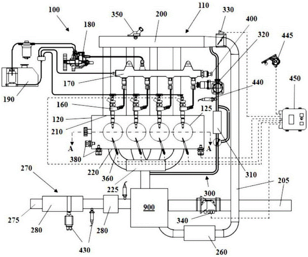
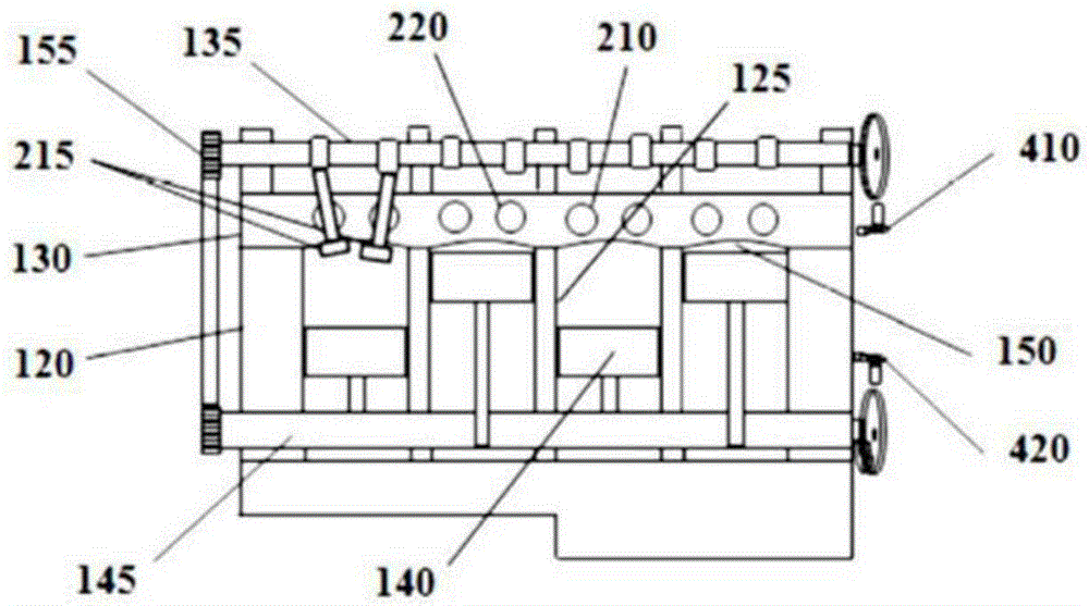
[0121] Some embodiments may include such as figure 1 with figure 2 The illustrated automotive system 100 includes an internal combustion engine (ICE) 110 having an engine block 120 defining at least one cylinder 125 having a piston coupled to rotate a crankshaft 145 140. Cylinder head 130 cooperates with piston 140 to define internal combustion engine 150 . A fuel and air mixture (not shown) is disposed in internal combustion engine 150 and is ignited, which produces thermally expanding exhaust gases that cause reciprocating motion of piston 140 . Fuel is provided through at least one fuel injector 160 and air is provided through at least one intake port 210 . Fuel is provided to fuel injector 160 at high pressure from fuel rail 170 in fluid communication with a high pressure fuel pump 180 that increases the pressure of fuel received...


PUM


Abstract

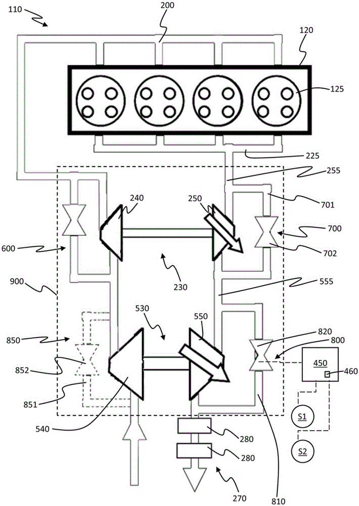
Disclosed is a two stage turbocharger 900 for an internal combustion engine 110, the two stage turbocharger 900 comprising a high pressure turbine 250 fluidly connected to an exhaust manifold 225 of the engine 110 through a high pressure turbine inlet duct 255 and a low pressure turbine 550 fluidly connected to the high pressure turbine 250 through a low pressure turbine inlet duct 555, wherein the low pressure turbine 550 is a variable geometry turbine, wherein the two stage turbocharger 900 comprise a bypass duct system 800 to bypass the variable geometry low pressure turbine, wherein the bypass duct system comprises a bypass valve 820, (855, figure 4). The variable geometry low pressure turbine 550 comprises a housing (560), and the bypass valve may be a housing-integrated bypass valve (855). A value is monitored of an operating parameter of said engine 110 during operation, wherein the operating parameter is engine speed and / or an engine torque correlated parameter. The bypass valve of the variable geometry low pressure turbine is operated when a monitored value is below, or equal to, a threshold value (e.g. especially at low speed or low loads of the engine).

Description

technical field [0001] The invention relates to an internal combustion engine with a two-stage turbocharger. Background technique [0002] Two-stage turbochargers for internal combustion engines are known in the art and include a high-pressure (HP) turbocharger and a low-pressure (LP) turbocharger, each turbocharger in turn A compressor is included that is rotationally coupled to a turbine. [0003] These turbocharger systems may be configured to operate both turbochargers at low / medium engine speeds and to operate only the LP turbocharger at high engine speeds. In this second case, the HP turbocharger is bypassed. [0004] Turbochargers allow for higher internal combustion engine performance. However, turbochargers have some disadvantages, especially when the internal combustion engine is operated at low speeds and / or low loads. [0005] The first disadvantage is that, as an example, non-negligible heat loss from the exhaust gas through the LP turbine casing, the substa...

Claims


Application Information

Patent Timeline
Patent Type & Authority Applications(China)
IPC IPC(8): F02B37/013F02B37/18F02B37/24F02B37/16
CPCF02B37/004F02B37/013F02B37/162F02B37/183F02B37/24F02D35/023F02D41/0007F02D2200/101Y02T10/12F02B37/005F02B37/12
Inventor A.莫加维罗F.洛萨诺C.M.米诺E.曼塔V.佩特伦兹
Owner GM GLOBAL TECH OPERATIONS LLC
Learn More