
A spiral disc belt type low temperature dryer device

A spiral disc and dryer technology, applied in heating devices, drying solid materials, local stirring dryers, etc., can solve the problems of unsuitable drying equipment, low production capacity, and large floor space.

Inactive Publication Date: 2018-05-08
张柱
View PDF8 Cites 0 Cited by
  • Summary
  • Abstract
  • Description
  • Claims
  • Application Information

AI Technical Summary

Problems solved by technology

The existing drying equipment is not suitable
The drying temperature is above 150-300 degrees, the energy consumption of preheating and work is high, and it is not suitable for drying heat-sensitive materials
In particular, the general heat-sensitive materials are dried with slurry with high moisture content, which brings certain difficulties to the drying of such materials.
The existing vacuum freeze-drying and low-temperature flat-plate dryers using hot water as the heat source have the disadvantages of slow speed, low production capacity, large floor space and high energy consumption, although they have the temperature requirements suitable for drying heat-sensitive materials. Not suitable for large-scale production requirements of low-temperature drying materials, let alone low-temperature drying of slurry materials with high moisture content

Method used


Image

  • A spiral disc belt type low temperature dryer device
  • A spiral disc belt type low temperature dryer device
  • A spiral disc belt type low temperature dryer device

Examples


Embodiment

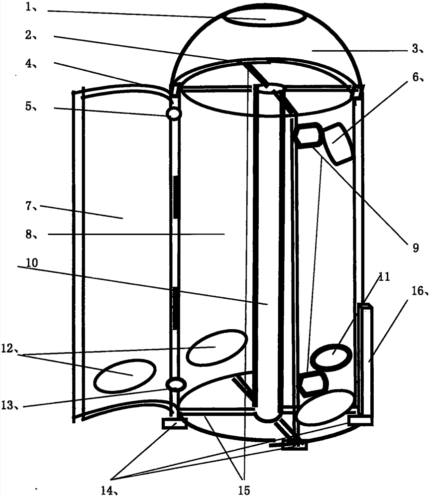
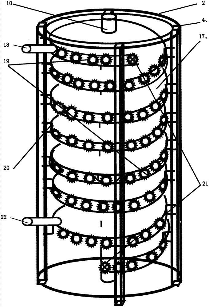
[0055] Embodiment: take radius 1.25 meters, spiral heat dissipation disk thickness 8cm, spiral layer spacing 20cm, accommodate 15 layers of spiral disks, device total height 4.48 meters of the device specifications of the present invention, carrying dry matter with a water content of 60% as an example. First press the 60% moisture content button on the console, (such as figure 1 Middle 16), the water supply pipe and the motor are automatically turned on, (such as figure 1 middle 9 and figure 2 , Figure 5 , Figure 9 9 and 22), the spiral drying plate starts to move helically along the surface of the heating plate at a predetermined speed. Open the inspection door, (such as figure 1 In 7), after confirming that all parts of the equipment are operating normally, close the inspection door. Open the supply pipe valve, (such as Figure 5 Middle 33), then the feeding nozzle starts to spray the dried material to the lower surface of the drying disc with a predetermined flow r...


PUM


Abstract

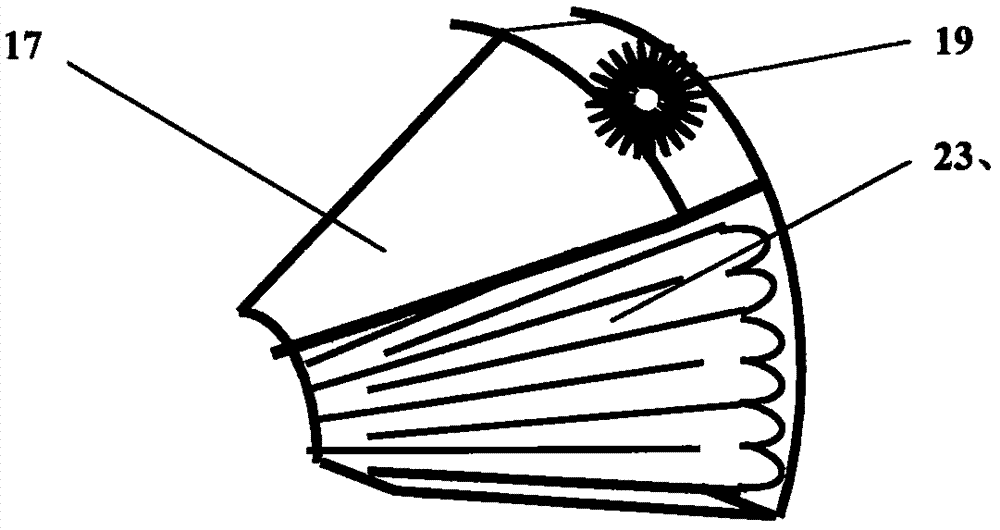
The invention discloses a helical coil belt-type low-temperature drier device being suitable for drying heat sensitive materials of which the moisture contents are 60 percent or higher. The helical coil belt-type low-temperature drier device mainly comprises ten systems such as a heat-insulating outer barrel and ventilation system, a helical heating coil system, a helical drying coil belt system, a heating coil and drying coil fitting system, a heating coil circulatory heating system, a drying coil belt movement power and control system, a feeding and material bearing system, a material receiving system, and a complete machine operation control system, wherein a cylindrical heat-insulating outer barrel comprises an up-down ventilation system; a fixed helical heating coil, which surrounds a central cylinder and is fixed on four upright posts in the wall of the outer barrel via an arch-shaped connection plate, is arranged in the heat-insulating outer barrel; 60 DEG C water flows in the helical heating coil in a circulatory manner for heating; a helical sector-shaped drying coil belt, of which the head is connected with the end, is attached on the helical heating coil; power traction holes in the outer end of the drying coil belt are occluded with driving wheels and transmission wheels on outer facades of the heating coil via pressing pinch plates; and under the driving of a driving motor, and interaction of stretching ball bearings in the drying coil belt, the drying coil belt performs helically circulatory and reciprocating movement along the surface of the heating coil, so that the materials attached on the drying coil belt can be dried continuously at a low temperature.

Description

technical field [0001] The invention relates to a spiral-drum type low-temperature dryer device, which belongs to the mechanical industry manufacturing industry. It is a low-temperature drying equipment for materials, which is suitable for drying materials that require a drying temperature limit of below 60 ° C, especially for heat-sensitive materials with a moisture content of 60% or more. Dry on low heat. Background technique [0002] The basic goal of material drying is to reduce the moisture content without destroying the active ingredient composition and content of the material and its physical and chemical properties. Therefore, the appropriate drying method and device must be selected according to the heating characteristics of the material object. Generally, heat-sensitive materials need to be dried below 60 degrees Celsius in order to protect the existence of active ingredients such as VC, VE, polysaccharides, adenosine, and biological aromatic hydroxyls, so as to ...

Claims


Application Information

Patent Timeline
IPC IPC(8): F26B9/06F26B23/10F26B25/02
CPCF26B9/085F26B23/10F26B25/02
Inventor 张柱
Owner 张柱
Learn More