

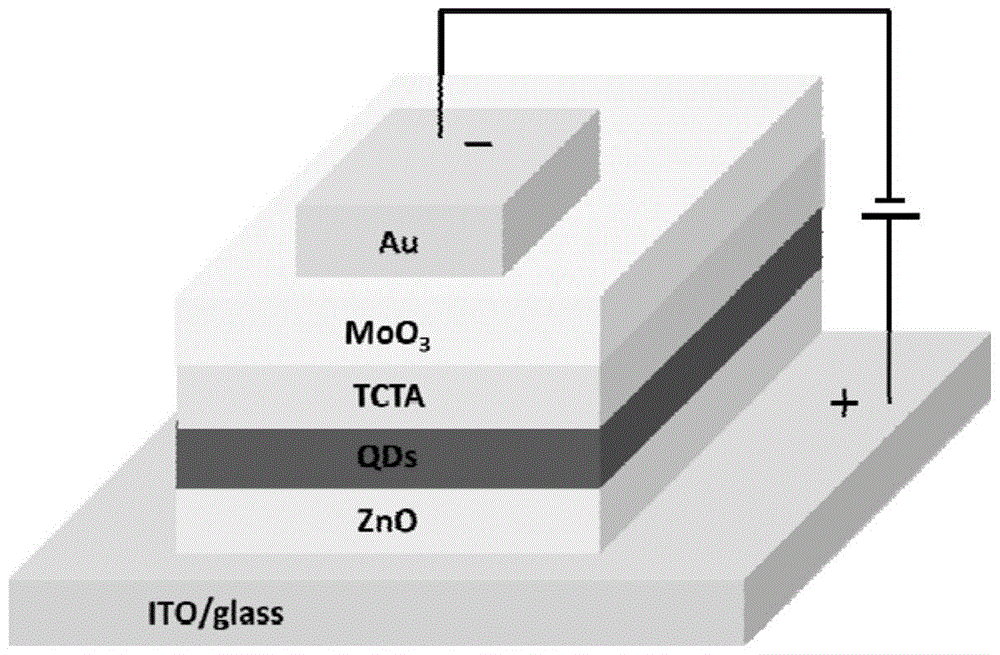
Inorganic perovskite quantum dot light-emitting diode with inverted structure
A technology of quantum dot light emission and inorganic calcium, which is applied in the direction of semiconductor devices, electrical components, circuits, etc., can solve the problems of performance deterioration, unfavorable, and hindering the development of flexible electroluminescent devices, and achieve high luminous efficiency, novel structure, and luminous wavelength Adjustable range of effects
- Summary
- Abstract
- Description
- Claims
- Application Information
AI Technical Summary
Problems solved by technology
Method used
Image

Examples
Embodiment 1
[0019] Step 1, magnetron sputtering deposition of ZnO on the cleaned ITO glass, the thickness is 40nm;
[0020] Step 2. Take 10mg / mL CsPbBr 3 The dispersion of quantum dots is spin-coated at a speed of 2000r / min;
[0021] Step 3, deposit TCTA by thermal evaporation method, the deposition thickness is 30nm;
[0022] Step 4. Deposit MoO by thermal evaporation 3 , The deposition thickness is 10nm;
[0023] Step 5: Deposit Au electrode with a mask plate by thermal evaporation method with a thickness of 100nm to obtain CsPbBr with reversed structure 3 Inorganic perovskite quantum dot light-emitting diodes.
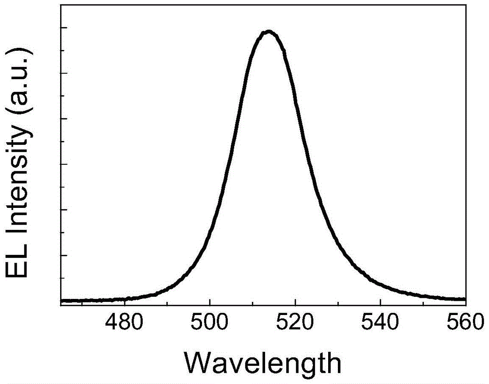
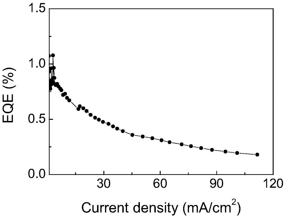
[0024] The CsPbBr of the inverted structure prepared in this embodiment 3 The electroluminescence spectrum of inorganic perovskite quantum dot light-emitting diodes is as follows figure 1 As shown, it can be seen that the FWHM of the luminescence peak is about 20nm, and the color purity is very high; the relationship between the current density and the external quantum efficiency is show...
Embodiment 2
[0026] Step 1. Magnetron sputtering deposition of ZnO on the cleaned ITO glass with a thickness of 30nm;
[0027] Step 2. Take 15mg / mL CsPbClBr 2 The dispersion of quantum dots is spin-coated at a speed of 2000r / min;
[0028] Step 3, deposit TCTA by thermal evaporation method, the deposition thickness is 20nm;
[0029] Step 4. Deposit MoO by thermal evaporation 3 , The deposition thickness is 5nm;
[0030] Step 5: Deposit Au electrode with a mask plate by thermal evaporation method, with a thickness of 80nm, to obtain CsPbClBr with reversed structure 2 Inorganic perovskite quantum dot light-emitting diodes.
Embodiment 3
[0032] Step 1. Magnetron sputtering deposition of ZnO on the cleaned ITO glass with a thickness of 50 nm;
[0033] Step 2. Take 10mg / mL CsPbBr 2 The dispersion of I quantum dots is spin-coated at a speed of 2000r / min;
[0034] Step 3, deposit TCTA by thermal evaporation method, the deposition thickness is 40nm;
[0035] Step 4, deposit MoO3 by thermal evaporation method with a deposition thickness of 20nm;
[0036] Step 5: Deposit Au electrode with a mask plate by thermal evaporation method with a thickness of 100nm to obtain CsPbBr with reversed structure 2 I inorganic perovskite quantum dot light-emitting diodes.
PUM
| Property | Measurement | Unit |
|---|---|---|
| Deposition thickness | aaaaa | aaaaa |
| Concentration | aaaaa | aaaaa |
| Deposition thickness | aaaaa | aaaaa |
Abstract
Description
Claims
Application Information