Method for preventing pore passages from being flooded with water in catalyst layer of fuel cell

A fuel cell and catalytic layer technology, applied to battery electrodes, circuits, electrical components, etc., can solve problems such as voltage loss, blockage, and inability to effectively protect micropores, so as to improve activity and stability and prevent flooding

Inactive Publication Date: 2016-06-29
XIAMEN UNIV
6 Cites 9 Cited by

AI-Extracted Technical Summary

Problems solved by technology

[0006] The purpose of the present invention is aimed at the micropores (<10nm) of porous catalysts (such as Pt/C and M/N/C) which are easily blocked by smaller molecules (water, alcohol) resulting...

Abstract

The invention discloses a method for preventing pore passages from being flooded with water in the catalyst layer of a fuel cell, and relates to fuel cells. The method comprises the following steps of 1, selecting a hydrophobing agent which does not block the catalyst pore passages according to the pore passage structure of the catalyst and the pore sizes; and 2, adding the hydrophobing agent into the catalyst slurry, thus allowing the hydrophobing agent to uniformly cover the surfaces of the particles to establish a waterproof gas-permeable membrane in the catalyst layer of the fuel cell, and thereby achieving the effect of preventing the pore passages from being flooded with water in the catalyst layer of the fuel cell. By screening the molecular weights and viscosities of the hydrophobing agent, and covering the hydrophobing agent on the surfaces of the catalyst particles, the waterproof gas-permeable membrane is established; and the waterproof gas-permeable membrane can effectively prevent the catalyst micropores from absorbing water and can also be oxygen-permeable, thus active sites in the pore passages are prevented from being flooded with water to the utmost extent, and the activity and stability of the cell are improved. The method is particularly applicable to the three-way M/N/C catalyst based more on micropores, and meanwhile also can be applied to the pores more than 10nm.

Application Domain

Technology Topic

Active siteViscosity +3

Image

  • Method for preventing pore passages from being flooded with water in catalyst layer of fuel cell
  • Method for preventing pore passages from being flooded with water in catalyst layer of fuel cell
  • Method for preventing pore passages from being flooded with water in catalyst layer of fuel cell

Examples

  • Experimental program(7)
  • Effect test(1)

Example Embodiment

[0017] Example 1
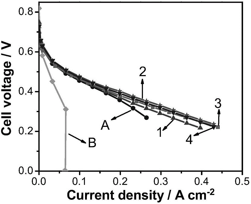
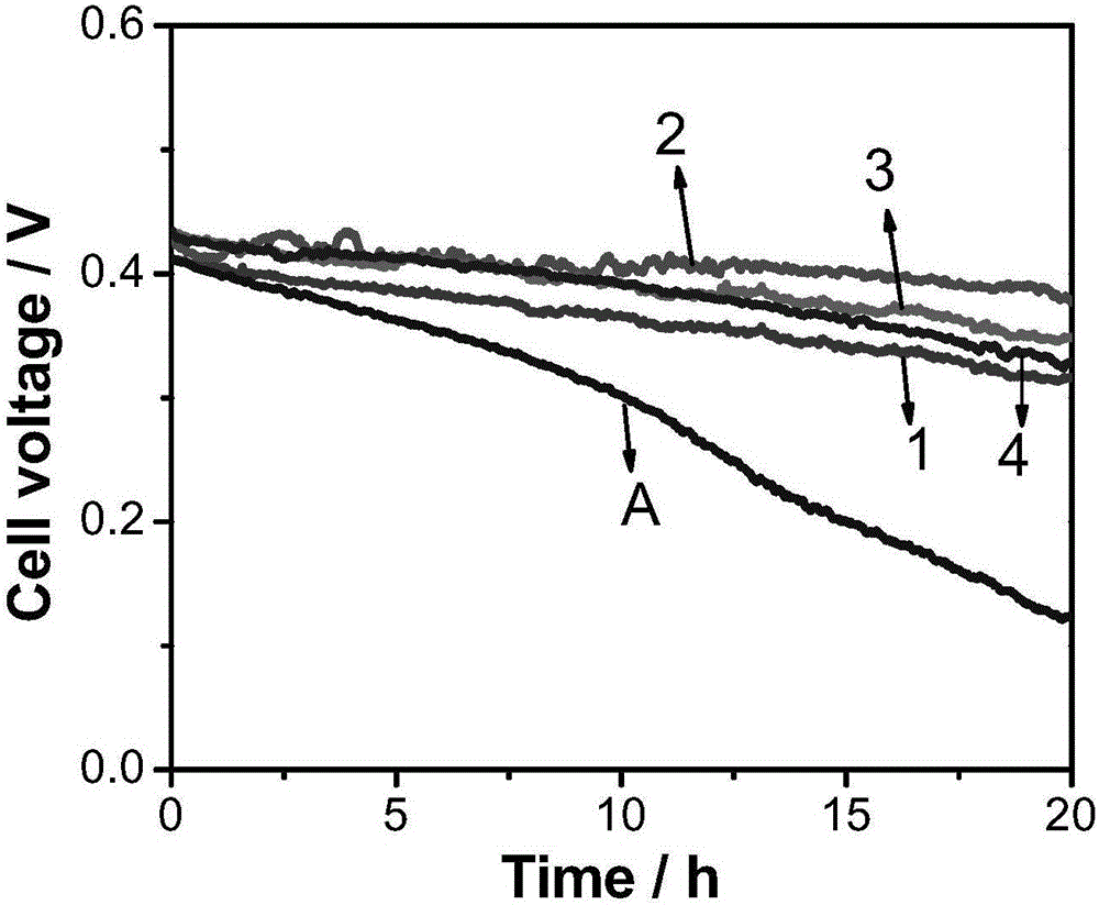
[0018] The molecular weight of dimethyl silicone oil is 9.4k; the viscosity is 200cp, which is used to prepare Fe/N/C ink;
[0019] Add simethicone (9.4kD, 200cp) to the cathode ink, the ink composition is: Fe/N/C catalyst 25mg; simethicone (9.4kD, 200cp) 50mg; 5wt% nafion solution 0.55mL; different solvents 1 mL of propanol; place the cathode ink in an ice-water bath and sonicate until it is uniformly dispersed; prepare the gas diffusion electrode (GDS) by drip coating, and the final cathode catalyst load is 5mgcm -2;
[0020] The preparation method of the anode gas diffusion electrode is similar to that of the cathode. The ink composition is Pt-Ru/C (40wt%Ptand20wt%Ru, JohnsonMatthey)-20mg; 5wt% nafion solution 0.22mL; deionized water 0.2mL; isopropanol 0.4mL; Place the cathode ink in an ice-water bath and ultrasonic for 10 minutes; prepare the gas diffusion electrode (GDS) by drip coating, and the final anode metal load is 4mgcm -2;
[0021] The prepared gas diffusion electrode and nafion membrane are hot pressed to form a membrane electrode (the hot pressing condition is 135℃, 3MPa, 2min); the prepared membrane electrode assembly cell is tested for single cell, the test condition is: Arbin methanol fuel cell test System; Oxidizer: unhumidified oxygen (100sccm); Fuel: 3M methanol aqueous solution (2sccm); Cell temperature: 60°C.

Example Embodiment

[0022] Example 2
[0023] The molecular weight of dimethyl silicone oil is 28k; the viscosity is 1000cp, which is used to prepare Fe/N/C ink;
[0024] Add dimethyl silicone oil (28kD, 1000cp) to the cathode ink, the ink composition is: Fe/N/C catalyst 25mg; dimethyl silicone oil (28kD, 1000cp) 50mg; 5wt% nafion solution 0.55mL; solvent isopropanol 1mL; The cathode ink is placed in an ice water bath and sonicated until it is uniformly dispersed; the gas diffusion electrode (GDS) is prepared by drip coating, and the final cathode catalyst loading is 5mgcm -2;
[0025] The preparation method of the anode gas diffusion electrode is similar to that of the cathode. The ink composition is Pt-Ru/C (40wt%Ptand20wt%Ru, JohnsonMatthey)-20mg; 5wt% nafion solution 0.22mL; deionized water 0.2mL; isopropanol 0.4mL; Place the cathode ink in an ice-water bath and ultrasonic for 10 minutes; prepare the gas diffusion electrode (GDS) by drip coating, and the final anode metal load is 4mgcm -2;
[0026] The prepared gas diffusion electrode and nafion membrane are hot pressed to form a membrane electrode (the hot pressing condition is 135℃, 3MPa, 2min); the prepared membrane electrode assembly cell is tested for single cell, the test condition is: Arbin methanol fuel cell test System; Oxidizer: unhumidified oxygen (100sccm); Fuel: 3M methanol aqueous solution (2sccm); Cell temperature: 60°C.

Example Embodiment

[0027] Example 3
[0028] The molecular weight of F modified silicone oil is 30k; the viscosity is 1500cp, which is used to prepare Fe/N/C ink;
[0029] Add F modified silicone oil (30kD, 1500cp) to the cathode ink. The ink composition is: Fe/N/C catalyst 25mg; F modified silicone oil (30kD, 1500cp) 50mg; 5wt% nafion solution 0.55mL; solvent n-propanol 1mL; The cathode ink is placed in an ice water bath and sonicated until it is uniformly dispersed; the gas diffusion electrode (GDS) is prepared by drip coating, and the final cathode catalyst loading is 5mgcm -2;
[0030] The preparation method of the anode gas diffusion electrode is similar to that of the cathode. The ink composition is Pt-Ru/C (40wt%Ptand20wt%Ru, JohnsonMatthey)-20mg; 5wt% nafion solution 0.22mL; deionized water 0.2mL; isopropanol 0.4mL; Place the cathode ink in an ice-water bath and ultrasonic for 10 minutes; prepare the gas diffusion electrode (GDS) by drip coating, and the final anode metal load is 4mgcm -2;
[0031] The prepared gas diffusion electrode and nafion membrane are hot pressed to form a membrane electrode (the hot pressing condition is 135℃, 3MPa, 2min); the prepared membrane electrode assembly cell is tested for single cell, the test condition is: Arbin methanol fuel cell test System; Oxidizer: unhumidified oxygen (100sccm); Fuel: 3M methanol aqueous solution (2sccm); Cell temperature: 60°C.

PUM

PropertyMeasurementUnit
Viscosity>= 100.0cp
Viscosity200.0cp
Viscosity1000.0cp
tensileMPa
Particle sizePa
strength10

Description & Claims & Application Information

We can also present the details of the Description, Claims and Application information to help users get a comprehensive understanding of the technical details of the patent, such as background art, summary of invention, brief description of drawings, description of embodiments, and other original content. On the other hand, users can also determine the specific scope of protection of the technology through the list of claims; as well as understand the changes in the life cycle of the technology with the presentation of the patent timeline. Login to view more.

Similar technology patents

Method for synthesizing phosphatidylserine by using immobilized biocatalyst

PendingCN111778295AImprove activity and stabilityImprove work reliability and synthesis efficiencyHydrolasesOn/in organic carrierPhosphatidylserinesZno nanowires
Owner:上海云洛生物技术有限公司

Classification and recommendation of technical efficacy words

  • Prevent flooding
  • Improve activity and stability

Method and Apparatus for Capturing, Storing, and Distributing Storm Water

ActiveUS20120201603A1Promote sportsPrevent floodingMining devicesSoil drainageModularityStorm
Owner:OLDCASTLE PRECAST

Dust removing box and dust removing system with same

Owner:ZOOMLION ENVIRONMENTAL IND CO LTD

Multicast forwarding method and device

ActiveCN105530188AAccurate forwardingPrevent floodingData switching networksTraffic volumeMedia access control
Owner:HANGZHOU DPTECH TECH

Fuel cell vehicle

ActiveUS20120070757A1Prevent floodingWater management in fuel cellsValve openingEngineering
Owner:TOYOTA JIDOSHA KK

Falling-film type absorbing and condensing device and method

InactiveCN108722132AHighlight the characteristics of process intensificationPrevent floodingGas treatmentDispersed particle separationDual effectEngineering
Owner:羿太环保科技(上海)有限公司

Hydro-fining catalyst roasted at low temperature and preparation method thereof

InactiveCN102784656AImprove activity and stabilityLow cost of preparationPhysical/chemical process catalystsRefining to eliminate hetero atomsOxideFluid catalytic cracking
Owner:CHINA UNIV OF PETROLEUM (EAST CHINA)
Why Eureka
Try Eureka