Electric wire post welding device and working method thereof

A technology for welding devices and utility poles, which is applied in auxiliary devices, welding equipment, auxiliary welding equipment, etc., can solve the problem of inability to accurately adjust the levelness, height and concentricity of wire poles at the same time, and the lack of adjacent steel pipe clamping and adjustment facilities , unable to ensure alignment and welding quality, etc., to achieve the effect of saving manpower, convenient welding, convenient installation and disassembly

Inactive Publication Date: 2016-07-06
STATE GRID SHANDONG ELECTRIC POWER CO LAIZHOU POWER SUPPLY CO
View PDF7 Cites 10 Cited by
  • Summary
  • Abstract
  • Description
  • Claims
  • Application Information

AI Technical Summary

Problems solved by technology

But the present invention lacks the clamping and adjusting facilities of adjacent steel pipes
[0007] To sum up the above, the existing technology cannot accurately adjust the levelness, height and concentricity of the wire rod at the same time, the degree of automation of welding is l

Method used


Image

  • Electric wire post welding device and working method thereof
  • Electric wire post welding device and working method thereof
  • Electric wire post welding device and working method thereof

Examples


Example Embodiment

[0058] The technical content of the present invention is described below through specific specific embodiments, and those skilled in the art can easily understand other advantages and effects of the present invention from the content disclosed in this specification. The present invention can also be implemented or applied through other different specific embodiments. The details in this specification can also be based on different viewpoints and applications, and various modifications and changes can be made without departing from the spirit of the present invention.
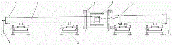
[0059] See figure 1 , Which is a schematic diagram of the actual work of an embodiment of the present invention assembled.

[0060] The utility pole welding device shown in the figure includes a utility pole clamp plate with two semicircular cavities, a utility pole support 2, a level measuring device, and a utility pole tensioning device. The utility pole support 2 includes The bottom bracket 21, the middle bracket ...


PUM


Abstract

The invention discloses an electric wire post welding device and a working method thereof. The electric wire post welding device comprises an electric wire post clamp plate provided with two semicircular cavities. The circular arc diameter of the electric wire post clamp plate is matched with the outer diameter of a reinforced electric wire post. The electric wire post welding device further comprises electric wire post support seats, a levelness measurement device, an electric wire post tension device and an electric conduction sliding ring. Each electric wire post support seat comprises a bottom layer support, a middle layer support and an upper layer support which are connected movably from bottom to top. A speed reducing motor and an electric welding machine lead support seat are installed on support wheels of one electric wire post support seat. According to the electric wire post tension device, two clamping stirrups pull close two segments of electric wire posts through tension screws. According to the electric wire post welding device and the working method thereof, the production cost can be reduced. Through usage of an electric driving device and the electric conduction sliding ring, the automation degree is improved. The levelness, the height and the concentricity of the butt welded electric wire posts can be adjusted through the electric wire post support seats, so that the welding quality of the butt welded electric wire posts can be ensured, and safety accidents are prevented.

Description

technical field [0001] The invention relates to a utility pole welding device and a working method thereof. Background technique [0002] In the welding process of utility poles, a large number of construction workers are often required to transport and arrange the poles, and then perform butt welding. The number of personnel required is large, the labor intensity is high, and time-consuming and labor-intensive. The progress of the butt welding rod directly affects the progress and quality of the project, so a reasonably designed electric pole welding device is needed. [0003] Electricity poles are heavy, so it is generally necessary to transfer the poles to the welding frame by means of external forces such as cranes. Sometimes the storage location of the poles is relatively remote, and external means such as cranes cannot be used. Sometimes, the number of wire poles to be welded is relatively small, and the cost of dispatching a crane or renting a car seems to be high, ...

Claims


Application Information

Patent Timeline
IPC IPC(8): B23K37/047B23K37/053
CPCB23K37/00B23K37/04B23K37/047B23K37/0533
Inventor 郑立军林晓兵谢永卫周绍芬杨景茹牟云浩
Owner STATE GRID SHANDONG ELECTRIC POWER CO LAIZHOU POWER SUPPLY CO
Why Eureka
Try Eureka