Electromagnetic piling device and electromagnetic piling method

A piling device and electromagnetic technology, applied in sheet pile wall, construction, infrastructure engineering and other directions, can solve the problems of high soil layer requirements, noise self-weight, etc., and achieve the effect of reducing equipment self-weight, fast piling speed, and simple construction

Active Publication Date: 2016-07-06
HUAZHONG UNIV OF SCI & TECH
View PDF9 Cites 7 Cited by
  • Summary
  • Abstract
  • Description
  • Claims
  • Application Information

AI Technical Summary

Problems solved by technology

[0003] Aiming at the above defects or improvement needs of the prior art, the present invention provides an electromagnetic piling device and method, the purpose of which is to provide a pile foundation construction with a light structure, simple operation, high efficiency, no noise, safe and reliable, and uses various The piling device for the soil layer solves the noise and vibration problems existing in traditional hammer piling and the technical problems of static pressure piling equipment that require high soil layers due to high self-weight

Method used


Image

  • Electromagnetic piling device and electromagnetic piling method
  • Electromagnetic piling device and electromagnetic piling method
  • Electromagnetic piling device and electromagnetic piling method

Examples


Embodiment 1

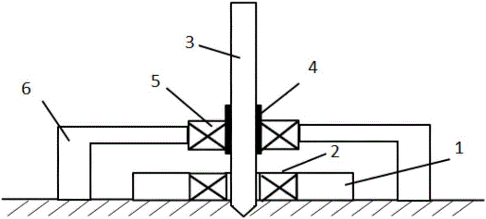
[0039] Such as figure 1 As shown, the overall structure of the electromagnetic piling in the embodiment of the present invention includes: a base 1 , a ground coil set 2 , a pile body 3 , a clamping mechanism 4 , a pile body coil set 5 , and a bracket 6 .

[0040] The base is arranged on the ground for installing the ground coil group and supporting the clamping mechanism; there is a pile hole in the middle of the base, and a groove is provided on the outer edge of the pile hole, and the ground coil group is installed in the groove (see Figure 6 ); the clamping mechanism is fixed on the base or the ground through a bracket; the clamping mechanism is used to clamp or release the pile body; The outside of the mechanism is arranged coaxially with the ground coil group, and the distance is relatively close to ensure sufficient electromagnetic force between the two coil groups.

[0041] The electromagnetic piling method includes the following steps:

[0042] (1) Fix the ground c...

Embodiment 2

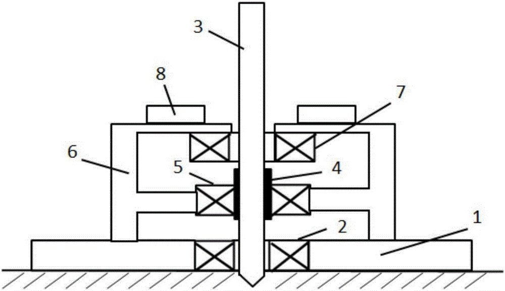
[0051] Such as figure 2 As shown, the overall structure of the electromagnetic piling of the embodiment of the present invention includes: a base 1, a ground coil group 2, a pile body 3, a clamping mechanism 4, a pile body coil group 5, a bracket 6, a first auxiliary coil group 7, and Weight 8.

[0052] The electromagnetic piling method includes the following steps:

[0053] (1) Fix the ground coil set 2 on the base 1 by bolts.

[0054] (2) The first auxiliary coil group 7 is fixed on the stand 6 by bolts, and the counterweight 8 is installed on the support 6 .

[0055] (3) Pass the pile body 3 through the first auxiliary coil group 7 and place it in the aperture of the coil group 7 .

[0056] (4) Hold the clamping mechanism 4 tightly to the pile body 3 , and the pile body coil group 5 is fastened to the pile body 3 through the clamping mechanism 4 .

[0057] (5) The clamping mechanism 4 realizes its own free movement up and down through the guide rail on the bracket 6 . ...

Embodiment 3

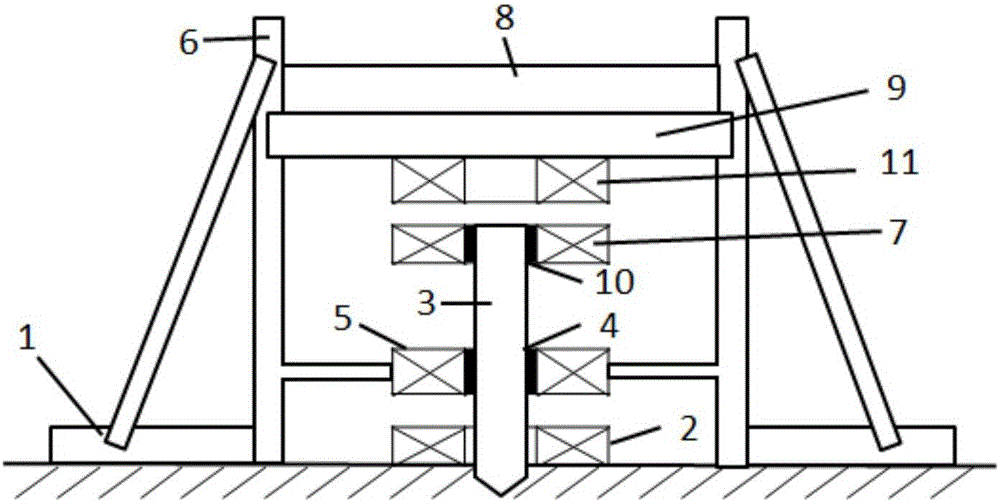
[0064] Such as image 3 As shown, the overall structure of the electromagnetic piling of the embodiment of the present invention includes: a base 1, a ground coil group 2, a pile body 3, a clamping mechanism 4, a pile body coil group 5, a bracket 6, a first auxiliary coil group 7, and Weight 8, top plate 9, second clamping mechanism 10, second auxiliary coil group 11.

[0065] The electromagnetic piling method includes the following steps:

[0066] (1) Fasten the first auxiliary coil group 7 to the pile body 3 through the second clamping mechanism 10 .

[0067] (2) Adjust the second auxiliary coil set 11 directly above the first auxiliary coil set 7 through the top plate 9 and the bracket 6 , and the top plate 9 is used to fix the second auxiliary coil set 11 .

[0068] (3) After the position adjustment of the second auxiliary coil group 11 is completed, the counterweight 8 is placed on the top plate 9 .

[0069] (4) In the piling process, the second auxiliary coil group 11...


PUM


Abstract

The invention discloses an electromagnetic piling device and an electromagnetic piling method. The electromagnetic piling device comprises a base, a ground coil assembly, a pile, a pile clamping mechanism and a pile coil assembly. The electromagnetic piling device and the electromagnetic piling method have the advantages that impact force / static pressures which are generated during traditional piling can be completely replaced by electromagnetic repulsive / attractive force generated between the coil assemblies; different current waveforms are designed, accordingly, the electromagnetic piling force can be flexibly controlled, and the optimal piling effects can be realized; the current waveforms can be selected, so that the single piling speed can be increased, the piling efficiency can be enhanced, and the electromagnetic piling device is little in vibration and influence on surrounding soil masses; the electromagnetic piling device and the electromagnetic piling method are provided on the basis; the electromagnetic piling device is free of pollution, low in noise, convenient to mount, easy to construct, high in adaptability, expansibility and safety coefficient, is free of influence of soil properties and pile types and is particularly applicable to municipal construction and night construction requirements, in particular to pile foundation engineering in crowded building places, high-rise buildings and buildings with narrow spaces.

Description

technical field [0001] The invention belongs to the field of pile foundation construction, and more specifically relates to an electromagnetic piling device. Background technique [0002] At present, the traditional piling methods mainly include the hammering method and the static pressure method. The hammering method pulls up the impact hammer through the traction device (hoist), repeatedly falls and lifts, and hits the pile foundation to realize piling. The construction of the hammering method is simple, and the cost of the piling machine manufactured by this method is cheap, but the construction noise is very large, the vibration is strong, and the piling is easy to affect the nearby buildings and soil layers, and the lifting position of the pile hammer is usually high, which has the advantages of Certainly dangerous. The static pressure method mainly uses the self-weight of the pile-pressing mechanism and the counterweight on the pile frame as the reaction force to pres...

Claims


Application Information

Patent Timeline
Patent Type & Authority Applications(China)
IPC IPC(8): E02D7/06E02D7/20
CPCE02D7/06E02D7/20
Inventor 李亮黄玉杰曹全梁赖智鹏蔡宏韩小涛
Owner HUAZHONG UNIV OF SCI & TECH
Why Eureka
Try Eureka