Fluid transport device and multiphase flow separating device
A separation device and multi-phase flow technology, applied in the field of multi-phase flow separation, can solve the problems of reducing generator life, generator wear, demagnetization, etc., and achieve the effect of reducing equipment damage and meeting the needs of use.
- Summary
- Abstract
- Description
- Claims
- Application Information
AI Technical Summary
Problems solved by technology
Method used
Image

Examples
Embodiment 1
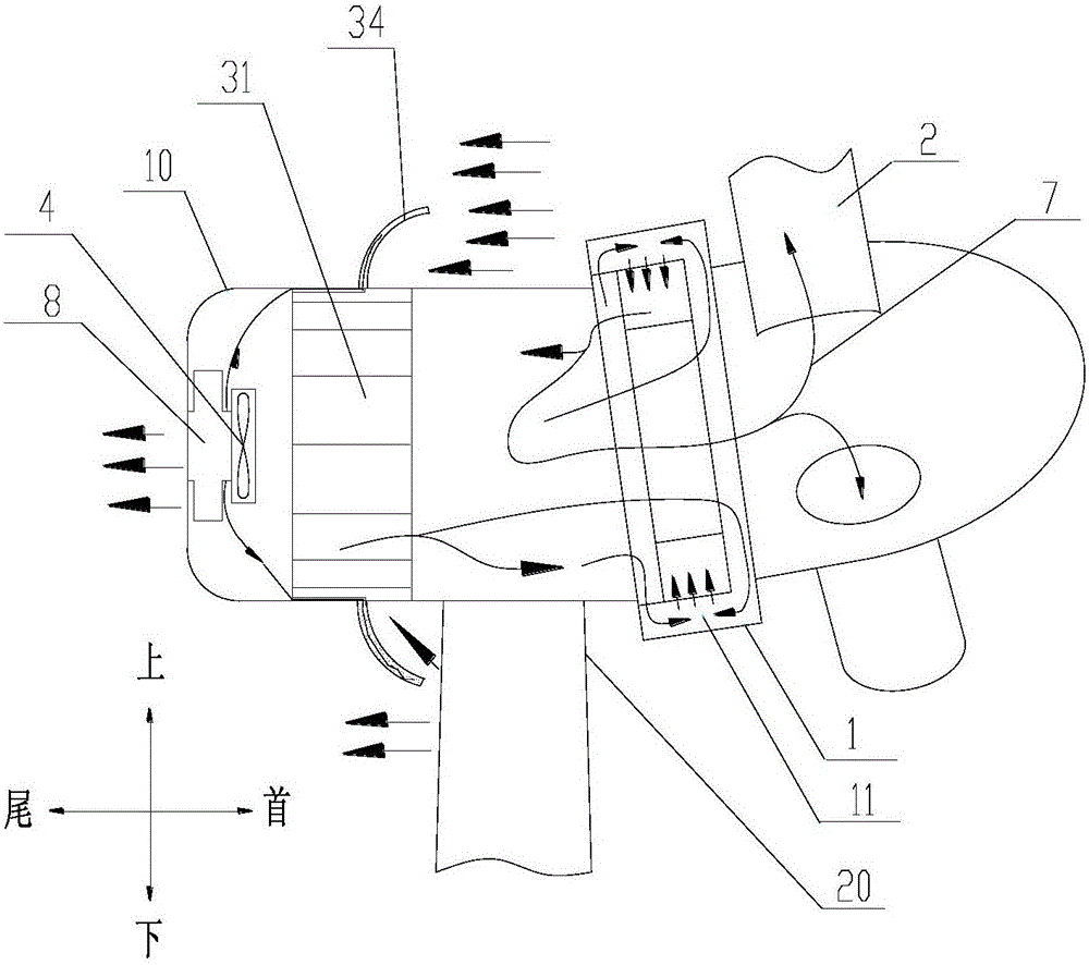
[0095] Such as figure 1 and figure 2 As shown, in the first specific embodiment, the exhaust fan 4 and the noise absorbing device 8 can be arranged at the rear of the nacelle 10 of the wind power generator system, and the above-mentioned multiphase flow separation device 3 can be located between the exhaust fan 4 and the exhaust device 9 Upwind direction: the exhaust fan 4 , the noise absorbing device 8 and the exhaust device 9 can be connected in sequence along the upwind direction. At the same time, the air outlet of the air exhaust device 9 can be set as flared, so as to improve the air exhaust efficiency and reduce the air exhaust noise. The air exhaust device 9 can also make the exhaust wind roughly parallel to the upwind direction and be discharged from the tail of the nacelle 10. It can be seen from fluid mechanics that the area at the tail of the nacelle 10 extending a certain distance along the upwind direction is basically a sound-absorbing zone. When the air exhau...
Embodiment 2
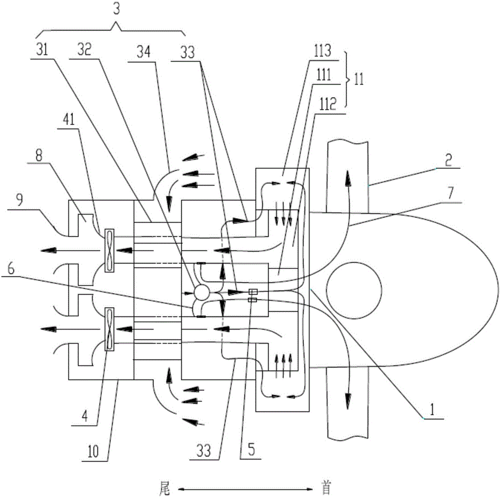
[0100] Please refer to Figure 12 and Figure 13 , in the second specific embodiment, the exhaust fan 4 and the noise absorbing device 8 can be arranged on the side of the nacelle 10 of the wind power generator system. At this time, the multiphase flow separation device 3 is located between the exhaust fan 4 and the exhaust device 9 The downwind direction; the side of the nacelle 10 is relative to the upwind direction, that is, the side that is in the upwind direction, or not in the fore-and-aft direction, and specifically can be a direction perpendicular to the upwind direction. At this time, in order to avoid mutual interference between the upwind incoming flow and the exhaust of the exhaust device 9, the air inlet of the multiphase flow separation device 3 can be approximately perpendicular to the air outlet of the exhaust device 9, or at a predetermined angle, usually the predetermined angle Greater than 80 degrees.
[0101] It should be noted that, in this article, when...
PUM
 Abstract
Description
Claims
Application Information
 - Generate Ideas
- Intellectual Property
- Life Sciences
- Materials
- Tech Scout
- Unparalleled Data Quality
- Higher Quality Content
- 60% Fewer Hallucinations
Browse by: Latest US Patents, China's latest patents, Technical Efficacy Thesaurus, Application Domain, Technology Topic, Popular Technical Reports.
© 2025 PatSnap. All rights reserved.Legal|Privacy policy|Modern Slavery Act Transparency Statement|Sitemap|About US| Contact US: help@patsnap.com