Ion conductivity test apparatus and test method employing same

A technology of ionic conductivity and testing device, applied in the direction of measurement device, measurement of electrical variables, measurement of resistance/reactance/impedance, etc., can solve the problem of inability to separate electronic conductivity, etc., and achieve the effect of accurate measurement method

Active Publication Date: 2016-07-13
DALIAN INST OF CHEM PHYSICS CHINESE ACAD OF SCI
View PDF5 Cites 4 Cited by
  • Summary
  • Abstract
  • Description
  • Claims
  • Application Information

AI Technical Summary

Problems solved by technology

[0003] Aiming at the deficiency that the electronic conductivity cannot be separated in the existing ionic conductivity testing technology, the present invention designs and prepares a four-electrode testing device using an ion conductor without electronic conductivity function as the test collector, which effectively separates the electronic conductivity of the electrode material. Excellent electronic conductivity and ionic conductivity, and is applicable to various materials and structures including carbon materials, metal materials, semiconductor materials, homogeneous, porous, etc.

Method used


Image

  • Ion conductivity test apparatus and test method employing same
  • Ion conductivity test apparatus and test method employing same
  • Ion conductivity test apparatus and test method employing same

Examples


Embodiment 1

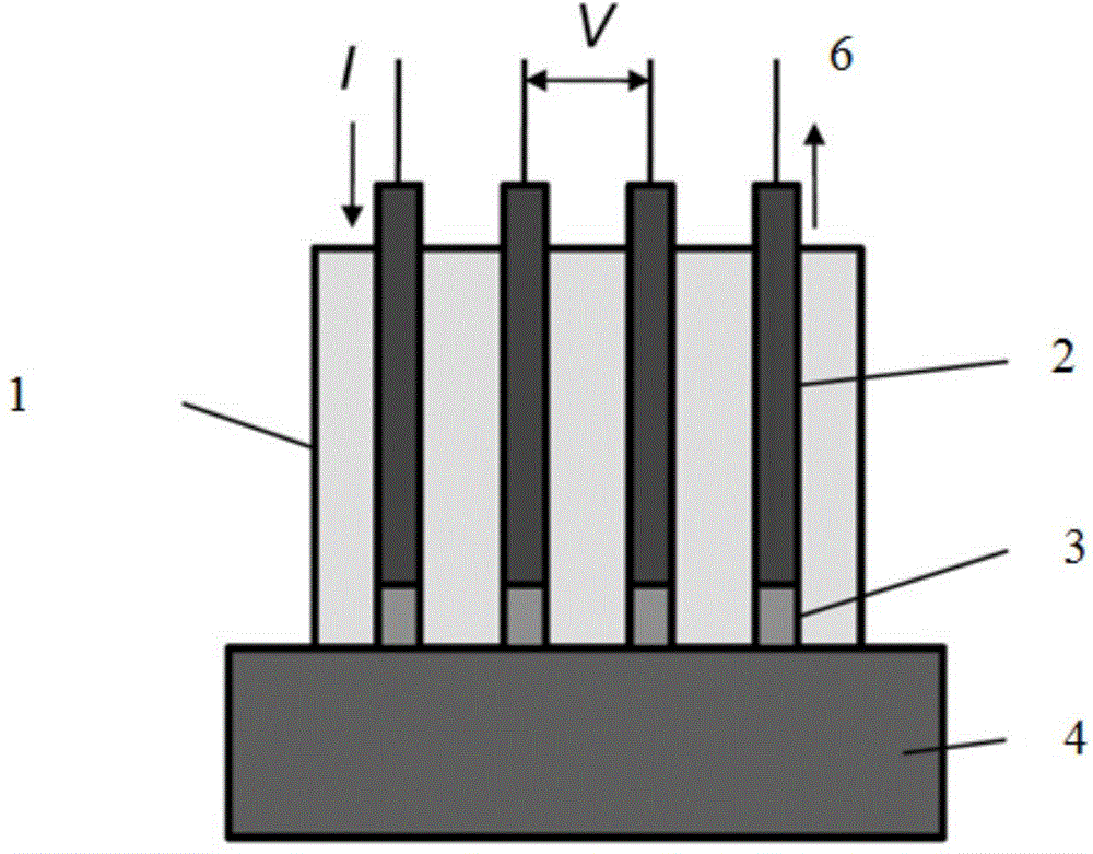
[0028] The schematic diagram of the test device is as figure 1 As shown, on a cylindrical polytetrafluoroethylene block with a diameter of 2 cm, 4 through holes arranged linearly along the central axis are machined, each with a diameter of 1 mm and a distance between the origins of 3 mm. Fix four platinum wires with the same diameter as the circular hole in the hole, and the distance between the end face of the platinum wire and the end face of the polytetrafluoroethylene block is 1 mm. Drop-coat 5% Nafion polyion solution on the end surface of the platinum wire, and apply it repeatedly after drying until the solid Nafion polymer completely covers the end surface of the platinum wire.

[0029] The test circuit is that the middle two platinum wires are externally connected to the voltage test terminals of the potentiostat (reference electrodes 1 and 2), and the two outer platinum wires are externally connected to the current test terminals (working electrode and counter electro...

Embodiment 2

[0038] The testing device is the same as that in Example 1.

[0039] a. Measurement of sample ion conductance:

[0040] Divide the moistened size to 5 x 5cm 2 The Nafion115 membrane and the above-mentioned test electrode have one end of the Nafion polymer tightly pressed against the surface of the sample to be tested. Use a potentiostat to apply a linear potential signal at the voltage test terminal, the voltage range is -1 to 1V, and record the current response signal at the current test terminal.

[0041] b. Data processing:

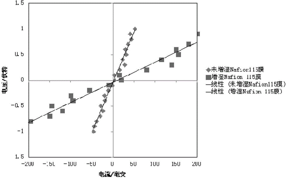
[0042] Taking the above-mentioned measured current signal as the abscissa and the voltage as the ordinate to plot, an approximate linear curve can be obtained, such as figure 2 shown. A linear fitting is carried out at a section with better linearity near the zero potential, and the slope d of the obtained fitting curve is the test ionic resistance of the sample to be tested.

[0043] According to the geometric structure of the probe electrode us...

Embodiment 3

[0047] The testing device is the same as that in Example 1.

[0048] a. Measurement of sample ion conductance:

[0049] Dimensions will be 5×5cm 2 The carbon paper and the above-mentioned test electrode have one end of the Nafion polymer tightly pressed against the surface of the sample to be tested. Use a potentiostat to apply a linear potential signal at the voltage test terminal, the voltage range is -1 to 1V, and record the current response signal at the current test terminal.

[0050] b. Data processing:

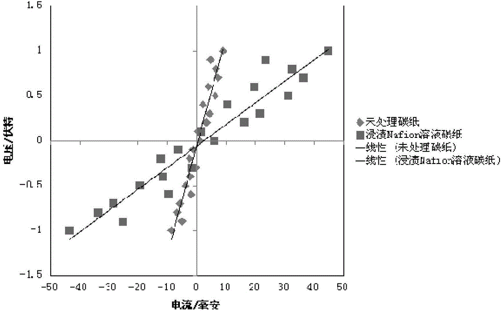
[0051] Taking the above-mentioned measured current signal as the abscissa and the voltage as the ordinate to plot, an approximate linear curve can be obtained, such as figure 2 shown. A linear fitting is carried out at a section with better linearity near the zero potential, and the slope d of the obtained fitting curve is the test ionic resistance of the sample to be tested.

[0052] According to the geometric structure of the probe electrode used in the test and...


PUM


Abstract

Disclosed is an ion conductivity test apparatus. The apparatus comprises a voltage / current test apparatus and a test electrode. The test electrode comprises a body substrate, four through holes in linear arrangement are arranged in the body substrate, and four platinum wires are respectively inserted into the through holes; the through holes between the end surfaces of the lower ends of the platinum wires and the lower surface of the body substrate are internally filled with ion conductor polymers. The ion conductor polymers are one from perfluosulfonic acid polymers, sulphonated poly(ether-ether-ketone), quaternized polysulfones and polybenzimidazoles. The ion conductivity test apparatus can be applied to measurement of the ion conductivity of any one from carbon paper, powered carbon, carbon fibers, semiconductors, metals and polymers. The method for detecting ion conductivity by use of the test apparatus comprises an ion conduction measurement step and a data processing step. The test apparatus and the method solve the problem of difficult measurement of the ion conductivity in an electronic conductor, a measurement result is quite accurate, and the conduction characteristic of ions in a material can be reflected.

Description

technical field [0001] The invention relates to a method for testing ion conductivity in electronic conductors, in particular to a method for testing ion conductivity in electrode materials. The method is accurate and efficient, and can meet the test requirements of various energy devices. Background technique [0002] The ion conduction efficiency in the electrode is closely related to the performance, life and cost of new energy technologies such as fuel cells, metal-air batteries, and lithium-ion batteries. It is one of the determinants of the electrode reaction rate and interface establishment. Therefore, the efficient detection of ionic conductivity is a key technology for the preparation of electrode materials and structures. Different from the ionic conductivity test method of polymer materials such as ordinary Nafion membranes, electrode materials have both electronic conductance and ionic conductance, and the two are difficult to separate, so metals such as platinu...

Claims


Application Information

Patent Timeline
IPC IPC(8): G01R27/14
Inventor 孙公权夏章讯王素力
Owner DALIAN INST OF CHEM PHYSICS CHINESE ACAD OF SCI
Why Eureka
Try Eureka