Average current control circuit and average current control method

A technology of average current control and average current, applied in control/regulation systems, conversion of DC power input to DC power output, electrical components, etc. It can solve the problem of limiting the application of average current control circuits, increasing circuit design complexity, and not applicable High-voltage application circuit and other problems, to achieve the effect of improving the current detection scheme, reducing the design difficulty, and excellent anti-noise performance

Inactive Publication Date: 2016-07-13
PEKING UNIV
View PDF5 Cites 7 Cited by
  • Summary
  • Abstract
  • Description
  • Claims
  • Application Information

AI Technical Summary

Problems solved by technology

However, limited by the control principle, the circuit structure is often complicated, the design is difficult, and the response speed is slow.
[0003] Common average current control circuits need to directly detect the current flowing through the inductor, so the sampling resistor must be connected in series with the inductor to detect the change of the voltage signal at both ends of the resistor. For step-down switching power supplies, no matter what topology is used, this Either end of the detection resistor will not be the actual ground, so if you want to detect the voltage change at both ends of the resistor, you can only res

Method used


Image

  • Average current control circuit and average current control method
  • Average current control circuit and average current control method
  • Average current control circuit and average current control method

Examples


Embodiment

[0058] This embodiment first describes the main frame structure of an average current control circuit provided by the present invention and the corresponding average current control method.

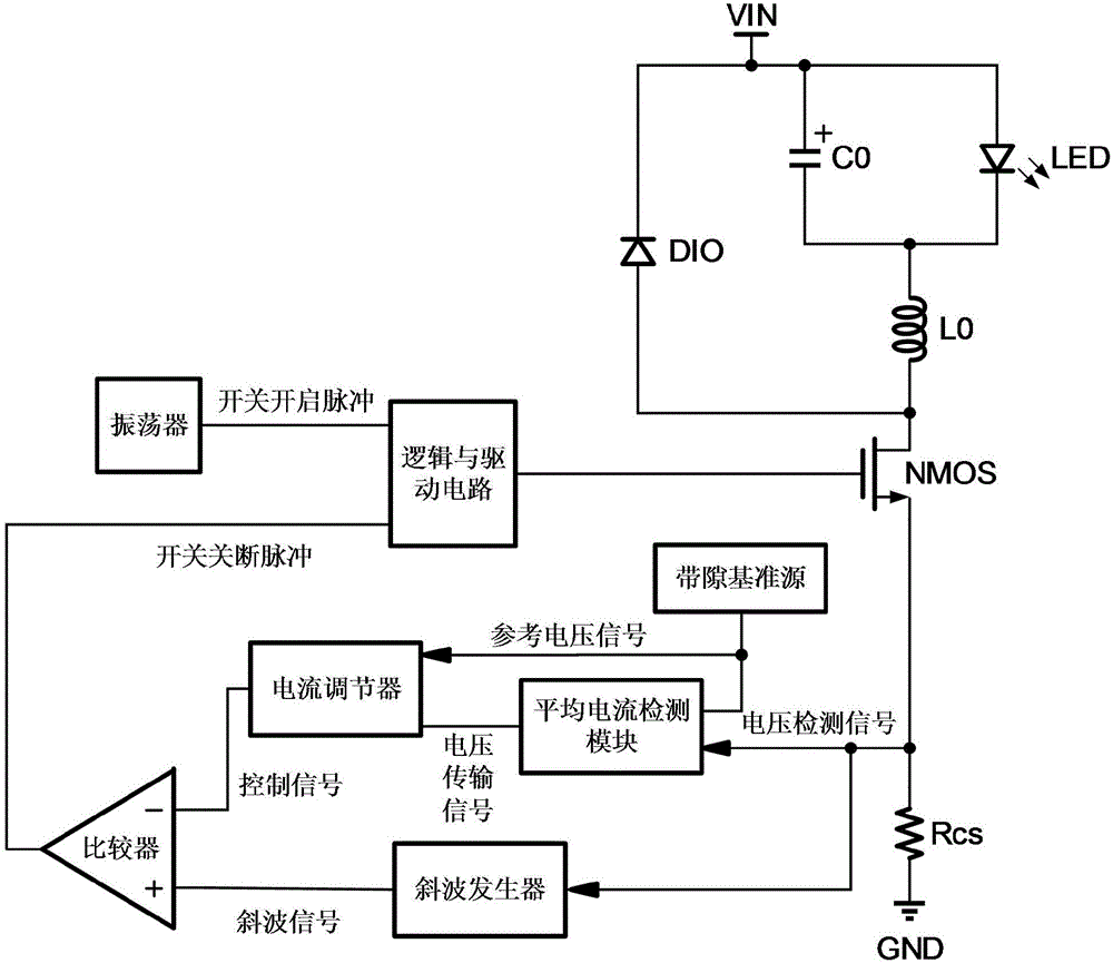
[0059] Such as figure 1 As shown, the average current control circuit includes load LED, power switch NMOS, inductor L0, capacitor C0, detection resistor Rcs, bandgap reference source, oscillator; comparator and logic and drive circuit;

[0060] In addition, the control circuit also includes:

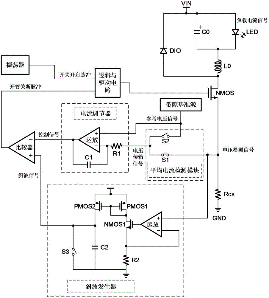
[0061] The current detection module is connected to the source end of the NMOS of the power switch and the non-ground end of the detection resistor Rcs during the turn-on period of the power switch to detect the current flowing through the NMOS of the power switch. The bandgap reference source;

[0062] The ramp generator is connected to the source end of the NMOS of the power switch and the non-ground end of the detection resistor Rcs during the turn-on period of the power switch to generate a v...


PUM


Abstract

The invention discloses an average current control circuit and an average current control method. In the circuit, one input terminal of an average current detection module is connected to a reference voltage signal output terminal of a band gap reference source, and another input terminal is connected to a source terminal of a power switch. A voltage transmission signal output terminal of the average current detection module is connected to an input terminal of a current regulator. Another input terminal of the current regulator is connected to the reference voltage signal output terminal of the band gap reference source, and an output terminal is connected to a negative input terminal of a comparator. An oblique wave generator input terminal is connected to the source terminal of the power switch, and an output terminal is connected to a positive input terminal of the comparator. An input terminal of a logic and driving circuit is connected to an output terminal of the comparator, another input terminal is connected to a switch starting pulse output terminal of an oscillator and an output terminal is connected to a grid terminal of the power switch. The source terminal of the power switch is connected to a grounding terminal via a detection resistor and a drain electrode is connected to a switch power supply module. Constant current precision is high, a current ripple wave is small and anti-noise performance is superior.

Description

technical field [0001] The invention belongs to the technical field of microelectronics and power management, and in particular relates to an average current control circuit and an average current conversion method. Background technique [0002] The average current control circuit is a common control scheme for constant current power supplies, and has important applications in energy-saving lighting circuits, screen backlights, high-power lighting and other fields. Compared with the peak current control circuit and the hysteresis current control circuit, the average current control mode circuit has the advantages of high control precision, small current ripple, and excellent anti-noise performance. However, limited by the control principle, the circuit structure is often complicated, the design is difficult, and the response speed is slow. [0003] Common average current control circuits need to directly detect the current flowing through the inductor, so the sampling resis...

Claims


Application Information

Patent Timeline
IPC IPC(8): H02M3/156H02M1/44
CPCH02M3/156H02M1/44
Inventor 李克之鲁文高陈中建张雅聪
Owner PEKING UNIV
Why Eureka
Try Eureka