High concentration gradient microfluidic mixing chip with jet flow damaging function

A high-concentration, gradient technology, applied in mixers, laboratory utensils, chemical/physical/physicochemical processes, etc., can solve problems such as reducing fluid concentration, low test reliability, and inability to detect low-sensitivity probes

Active Publication Date: 2016-07-20
SOUTHEAST UNIV
View PDF9 Cites 1 Cited by
  • Summary
  • Abstract
  • Description
  • Claims
  • Application Information

AI Technical Summary

Problems solved by technology

[0003] At present, most of the two-fluid microfluidic hybrid chips reduce the concentration of one of the fluids to 50%. For some applications, such as protein folding research, it is not enough to quickly and greatly reduce the concentration of denaturant to trigger the folding reaction.
Jet-based microfluidic mixers can significantly reduce the concentration of one of the fluids, but this type of mixer still has the problems of inability to detect low-sensitivity probes and low test reliability

Method used


Image

  • High concentration gradient microfluidic mixing chip with jet flow damaging function
  • High concentration gradient microfluidic mixing chip with jet flow damaging function
  • High concentration gradient microfluidic mixing chip with jet flow damaging function

Examples


Embodiment Construction

[0015] In order to solve the above-mentioned problems existing in the prior art, the applicant has conducted in-depth research and believes that the prior art has the following disadvantages:

[0016] 1. The size of the jet-type microfluidic mixing device is very small. Generally, the channel width is about 10um, and the formed jet is only 100nm, resulting in a very small detection area and high detection requirements. It is almost impossible to detect low-sensitivity probes, such as absorption and Raman. .

[0017] 2. The jet trajectory is determined by the experimental state, and the width is extremely narrow. Once the experimental state changes unpredictably, the jet will deviate from the predetermined trajectory, making it difficult to detect and the reliability of the experiment is low.

[0018] For this reason, the applicant proposes the following technical solutions.

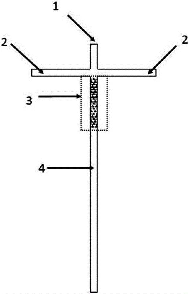
[0019] Such as figure 1 As shown, the jet-disrupting high-concentration gradient microfluidic mixing...


PUM


Abstract

The invention discloses a high concentration gradient microfluidic mixing chip with a jet flow damaging function.The microfluidic mixing chip comprises a center channel, side channels, a mixing channel and an outlet channel formed integrally with or communicated with the mixing channel; multiple rows of arc-edge triangular structures arrayed periodically are arranged in the mixing channel so that splitting, compounding and chaotic convection can be conducted on fluid, two arc edges of each arc-edge triangular structure are arcs of two unidiameter tangent circles, and the other edge of each arc-edge triangular structure is a tangent line of the two unidiameter tangent circles.Jet flow is damaged by the structure, the concentration of a diluted substance is substantially reduced, the diluted substance is uniformly distributed in the channels, it is not needed to trace the jet flow, detection difficulty is greatly reduced, and experiment reliability is improved.Meanwhile, the manufacturing process is simple, the mixing region structure can be formed just by conducting plane photoetching once, multiple exposure and alignment processes are not needed, and the manufacturing process is simplified.

Description

technical field [0001] The invention relates to a microfluidic mixing chip, in particular to a microfluidic mixing chip with a high-concentration gradient for jet flow destruction. Background technique [0002] In recent years, Lab-on-a-chip (Lab-on-a-chip) has been widely researched and applied in the fields of biology, chemistry, medicine, etc. Microfluidic mixer is an important part of it, and it must be used in the process of requiring rapid response. to a microfluidic mixer. [0003] At present, most of the two-fluid microfluidic hybrid chips reduce the concentration of one of the fluids to 50%. For some applications, such as protein folding research, it is not enough to quickly and greatly reduce the concentration of denaturant to trigger the folding reaction. Jet-based microfluidic mixers can significantly reduce the concentration of one of the fluids, but this type of mixer also has the problems of inability to detect low-sensitivity probes and low experimental reli...

Claims


Application Information

Patent Timeline
IPC IPC(8): B01F13/00B01J19/00B01L3/00
CPCB01J19/0093B01L3/5027B01F33/30
Inventor 朱利陈科祥陆辉崔一平
Owner SOUTHEAST UNIV
Why Eureka
Try Eureka