

Three-dimensional production system of prefabricated components
A prefabricated component and production system technology, applied in the direction of manufacturing tools, ceramic forming machines, ceramic forming workshops, etc., can solve the problems of high installation requirements for support wheels, increased land use area and workshop construction area, and limited workshop process layout. Achieve the effect of reducing the construction area of the plant, increasing the flexibility of production, and the layout of the production line
- Summary
- Abstract
- Description
- Claims
- Application Information
AI Technical Summary
Problems solved by technology
Method used
Image

Examples
Embodiment Construction
[0065] The present invention will be described in further detail below in conjunction with the accompanying drawings.
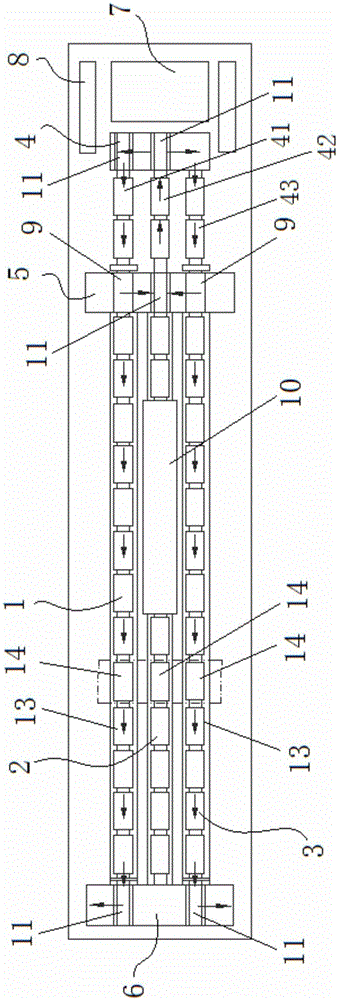
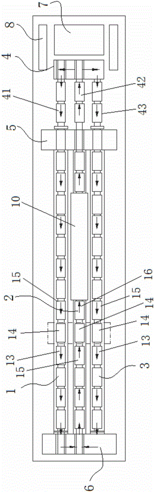
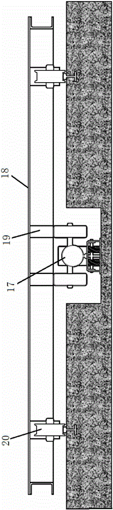
[0066] Such as Figure 1~2 and Figure 7-8As shown, the present invention includes an upper prefabricated component production area, a lower maintenance area and a wheeled formwork platform 18, wherein the upper prefabricated component production area includes a component prefabrication operation area, a component demoulding operation area and a side mold cleaning operation area 7, The component prefabrication operation area is provided with a dedicated production line and a production sub-line 2, and the component demoulding operation area is provided with an inversion cleaning sub-line and a side removal mold sub-line 42. The inversion cleaning sub-line and the component prefabrication operation area are dedicated The production line is connected, and the side mold removal sub-line 42 is connected with the production sub-line 2 of the component prefabricat...
PUM
 Abstract
Description
Claims
Application Information