Electromagnetic and piezoelectric combined fuel gas injection device

An injection device and a combined technology, applied in the direction of fuel injection devices, special fuel injection devices, oil supply devices, etc., can solve the problems of unsatisfactory engine power and series engine power requirements, limited response speed, gas injection pressure and injection rate Reduce problems such as meeting power and series engine power requirements, ensuring reliability and stability, and simplifying the engine structure

Active Publication Date: 2016-07-20
HARBIN ENG UNIV
View PDF4 Cites 1 Cited by
  • Summary
  • Abstract
  • Description
  • Claims
  • Application Information

AI Technical Summary

Problems solved by technology

[0003] The current in-cylinder direct injection gas injection system mainly controls the movement of the needle valve through the internal integrated high-speed solenoid valve to realize the opening and closing of the gas injection valve, which can control the timing and amount of gas injection, and has good energy saving and emission reduction effect, but there are some problems: first, the single-cylinder power coverage of the engine is large, and only the single-nozzle jet device is used to match the limited power of the engine, which cannot meet the power of the engine under different working conditions and the power requirements of serialized engines; , a single high-speed solenoid valve only has two working states of on and off, and cannot complete the multi-mode control of gas injection; third, the control of the solenoid valve is affected by the hysteresis loop and the inductance of the solenoid coil, and the response speed is limited; the control accuracy of the piezoelectric control valve High, fast response; Fourth, with the movement of the needle valve, the gas leaks upward along the gap between the needle valve coupler, and the leaked gas enters the control chamber, resulting in a decrease in the gas injection pressure and injection rate, which seriously affects the working stability of the gas injection device

Method used


Image

  • Electromagnetic and piezoelectric combined fuel gas injection device
  • Electromagnetic and piezoelectric combined fuel gas injection device
  • Electromagnetic and piezoelectric combined fuel gas injection device

Examples


Embodiment Construction

[0017] Below in conjunction with legend the present invention is described in more detail:

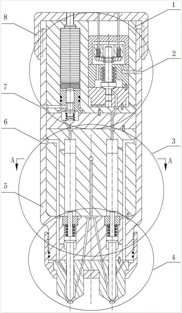
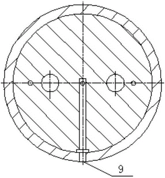
[0018] The combined electromagnetic-piezoelectric gas injection device of the present invention is mainly composed of an electromagnetic-piezoelectric control part 1, a double piston part 3, a double needle valve nozzle part 4, an injection device body 5 and an upper end cover 8 of the injection device. The injection device body 5 has a first low-pressure oil drain port 2, a control oil inlet 6, a second low-pressure oil drain port 7, a gas inlet 9, etc. The top view of the oil passage at the gas inlet is shown in Figure 1(b).

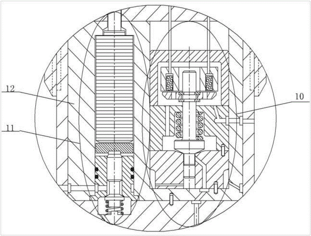
[0019]The electromagnetic-piezoelectric control part 1 mainly includes a solenoid valve 10 , a piezoelectric control valve 11 , a piezoelectric control valve sleeve 12 , etc. Both the solenoid valve 10 and the piezoelectric control valve 11 are installed in the piezoelectric control valve sleeve 12 . Solenoid valve 10 mainly comprises electromagnet 13, electrom...


PUM


Abstract

The invention provides an electromagnetic and piezoelectric combined fuel gas injection device. Gas injection is carried out by double needle valve nozzles to meet gas injection requirements under different working conditions of an engine, fuel gas injection processes of the two nozzles are controlled by an electromagnetic valve and a piezoelectric control valve respectively, and when the electromagnetic valve or the piezoelectric control valve works independently, only one nozzle is used for gas injection, and the control accuracy requirement of a low load of the engine on small-flow gas injection is met; when the electromagnetic valve and the piezoelectric control valve work simultaneously, the two nozzles are used for gas injection simultaneously, and the requirements of a high load of the engine on a gas injection amount and gas injection stability are met; and a sealing ring belt is designed between each needle valve and a corresponding needle valve seat above two needle valve cavities, a part of control oil is introduced to each sealing ring belt to seal a fuel gas through an oil channel, leakage of the fuel gas can be effectively prevented, the same oil is adopted as control oil in control cavities and sealing oil at the needle valves, and static leakage of fuel oil in the control cavities and the sealing ring belts can be effectively prevented.

Description

technical field [0001] The invention relates to a dual-fuel engine gas injection device, in particular to a combined electromagnetic-piezoelectric gas injection device. Background technique [0002] The development of engines is facing the dual pressure of energy crisis and environmental pollution. The use of alternative fuels is an effective means to solve both energy problems and environmental pollution. Natural gas and petroleum gas have become the main substitute fuels for internal combustion engines due to their abundant resources, low price, clean combustion, and high calorific value. [0003] The current in-cylinder direct injection gas injection system mainly controls the movement of the needle valve through the internal integrated high-speed solenoid valve to realize the opening and closing of the gas injection valve, which can control the timing and amount of gas injection, and has good energy saving and emission reduction effect, but there are some problems: firs...

Claims


Application Information

Patent Timeline
IPC IPC(8): F02M21/02
CPCF02M21/0248F02M21/0254F02M21/0263F02M2200/16F02M2200/44F02M2200/50Y02T10/30
Inventor 范立云彭怀利姚崇董全董晓露袁志国
Owner HARBIN ENG UNIV
Why Eureka
Try Eureka