Dehumidifying regenerative circulatory system

A circulatory system and regenerator technology, applied in the field of dehumidification, can solve problems such as reducing work efficiency, and achieve the effects of simple structure, reduced air flow resistance, and reduced energy consumption

Active Publication Date: 2016-07-20
GUILIN UNIV OF ELECTRONIC TECH
View PDF8 Cites 4 Cited by
  • Summary
  • Abstract
  • Description
  • Claims
  • Application Information

AI Technical Summary

Problems solved by technology

greatly reduced i

Method used


Image

  • Dehumidifying regenerative circulatory system
  • Dehumidifying regenerative circulatory system
  • Dehumidifying regenerative circulatory system

Examples


Example Embodiment

[0030] The principles and features of the present invention will be described below with reference to the accompanying drawings. The examples cited are only used to explain the present invention, and are not used to limit the scope of the present invention.

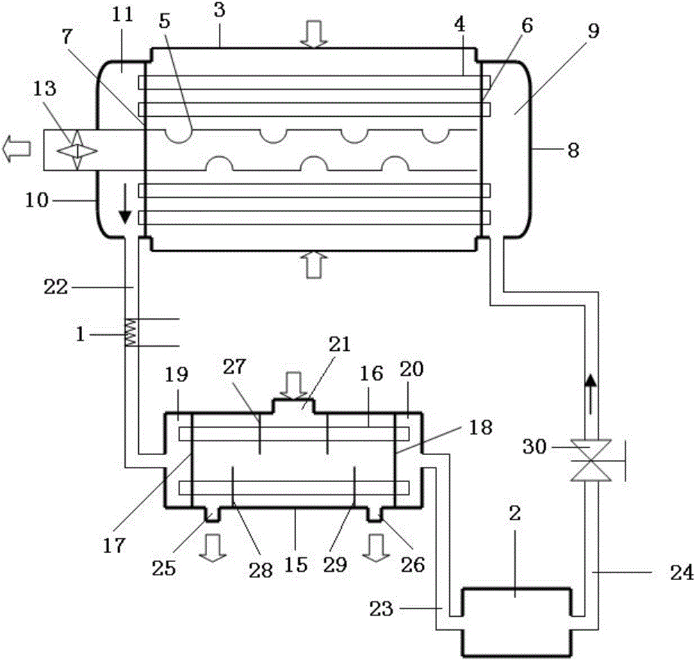
[0031] Such as figure 1 As shown, a dehumidification regeneration cycle system includes a closed loop composed of a dehumidifier, a heater 1, a regenerator, and a cooler 2 located in shallow underground; the heater 1 and the regenerator are used to connect The dehumidification solution after dehumidification and water absorption is concentrated, and the cooler 2 is used to cool the concentrated dehumidification solution, specifically as follows:
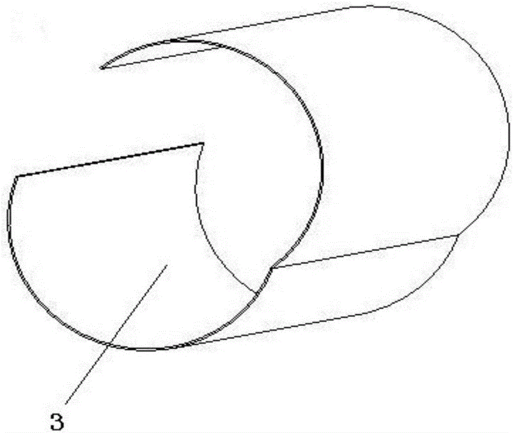
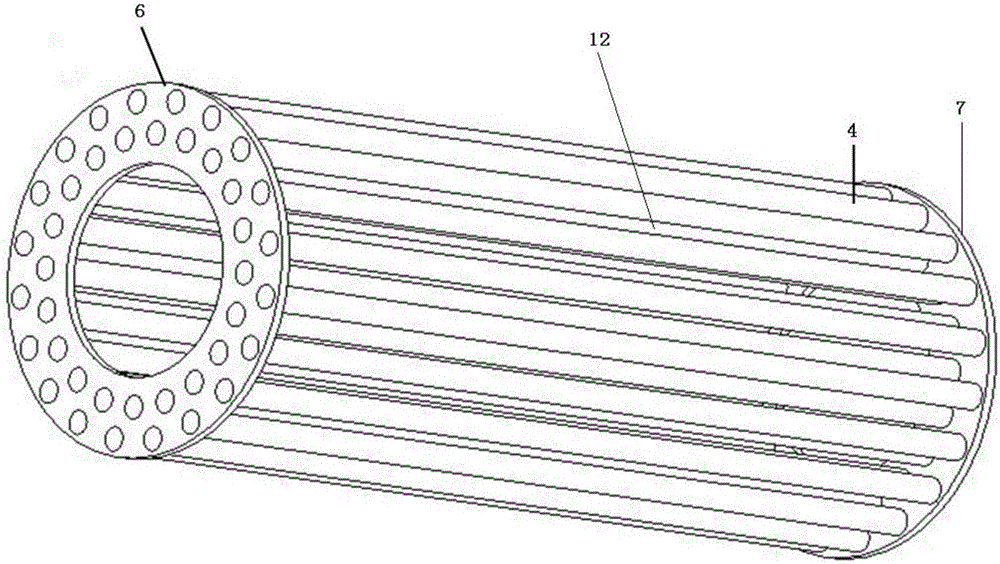
[0032] The dehumidifier includes a dust cover 3 with a hollow inside and made of air-permeable materials, a plurality of dehumidifying hollow fiber membrane tubes 4, and a cylindrical flow equalizing tube 5, respectively at the openings at both ends of the dust cover 3 A first blocki...


PUM


Abstract

The invention relates to a dehumidifying regenerative circulatory system. The system comprises a closed circulatory loop which is formed by successively connecting a dehumidifier, a heater, a regenerator and a cooler which is positioned in the underground of a shallow layer, wherein the heater and the regenerator are used for concentrating a dehumidification solution after dehumidification and water absorption, and the cooler is used for cooling the concentrated dehumidification solution. The system provided by the invention has the beneficial effects that as the closed circulatory loop is formed by successively connecting the dehumidifier, the heater, the regenerator and the cooler, the dehumidification solution can be repeatedly recycled; the high-temperature dehumidification solution flowing out of the regenerator with certain concentration is introduced to the cooler which is in the underground of the shallow layer, the temperature of the dehumidification solution is reduced to a temperature, at which a human body feels comfortable by using geothermal energy, and finally the dehumidification solution meeting the requirements flows into the dehumidifier to perform heat exchange and mass transfer with air; the obtained dried air which is appropriate in temperature flows into a house; as the geothermal energy is used, the energy consumption is greatly reduced, and the system plays roles of saving energy and protecting environment.

Description

technical field [0001] The invention relates to the field of dehumidification, in particular to a dehumidification regeneration circulation system. Background technique [0002] In 2013, my country's building energy consumption was about 1.05 billion tons of standard coal, accounting for about 28% of the energy consumption of the whole society. Air conditioning energy consumption accounts for about 50% of building energy consumption. Most areas in my country have high temperature and high humidity in summer, especially in South China, where dehumidification energy consumption accounts for 20%-40% of the total energy consumption of air conditioners, so the humidity control system is one of the core components of air conditioner energy consumption. Designing efficient and energy-saving air-conditioning and dehumidification systems is an urgent need for future social development. [0003] There are many methods of air dehumidification, including cooling dehumidification, liqu...

Claims


Application Information

Patent Timeline
IPC IPC(8): F24F3/14B01D53/26B01D53/14
CPCB01D53/263F24F3/1417F24F2003/144F24F2003/1458
Inventor 梁才航曾思
Owner GUILIN UNIV OF ELECTRONIC TECH
Why Eureka
Try Eureka