Totally closed loop cooler waste heat recovery device

A technology of waste heat recovery device and ring cooler, which is applied in waste heat treatment, lighting and heating equipment, treatment of discharged materials, etc., to achieve the effect of reducing heat consumption, reducing energy consumption and increasing energy utilization rate

Active Publication Date: 2017-09-19
MCC NORTH (DALIAN) ENG TECH CO LTD
View PDF7 Cites 0 Cited by
  • Summary
  • Abstract
  • Description
  • Claims
  • Application Information

AI Technical Summary

Problems solved by technology

At present, the utilization of heat at the material receiving port of the annular cooler is still blank in the industry

Method used


Image

  • Totally closed loop cooler waste heat recovery device

Examples


Embodiment Construction

[0024] The present invention will be further described in detail below in conjunction with the accompanying drawings and specific embodiments.

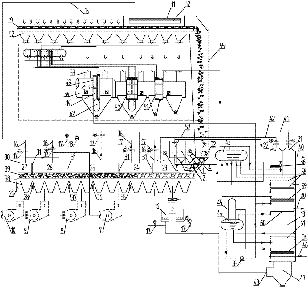
[0025] In this embodiment, the sintering machine 19 includes a sintering machine trolley, a transmission device, and sintered ore in the sintering machine trolley; the bottom of the sintering machine 19 is respectively provided with a bellows 52, a dust reduction pipe 53 and a sintering flue 54.

[0026] Such as figure 1 As shown, the receiving port 32 of the annular cooler 39 is directly welded to the first section 23 of the annular cooler, and the dust extraction point 1 at the receiving port 32 of the annular cooler 39 is connected to the dust collector 2 through the flue 15, and the flue 15 It is connected with the compensator of the dust collector 2 through a flange, and an air temperature regulating valve 4 is arranged on the inlet flue of the dust collector 2 . The bottom of the dust collector 2 is flange-connected to the cont...


PUM


Abstract

The invention belongs to the technical field of sintering ring cooling machine waste heat utilization, and relates to a totally-closed waste heat recycling device of a ring cooling machine. The totally-closed waste heat recycling device comprises a dust suction point. The dust suction point is connected with the input end of an overheater through a flue. The output end of the overheater is connected with the input end of a material receiving port high-temperature draught fan. The output end of the material receiving port high-temperature draught fan is connected with a high-parameter smoke inlet of a waste heat boiler. A smoke hood of a second section of the ring cooling machine is connected with a low-parameter smoke inlet of the waste heat boiler. The part, at the top of the ring cooling machine, of the smoke hood is divided by partition plates into a plurality of sections. A chimney of each section of the smoke hood is provided with a switching air door. Cooling draught fans are arranged at the bottom of the ring cooling machine. An inlet of each cooling draught fan is connected with the chimney of the rear section of the ring cooling machine, and an outlet of each cooling draught fan is connected with a communicating air flue and an ash falling hopper which are arranged at the bottom of the ring cooling machine. The chimneys, except for the chimneys on the first section of the ring cooling machine and the second section of the ring cooling machine, of the ring cooling machine are connected with an upper smoke hood of a material layer through a booster fan. The communicating air flues of the ring cooling machine are provided with adjusting air doors, and the communicating air flues connected with the cooling draught fans are isolated through the adjusting air doors.

Description

technical field [0001] The invention belongs to the technical field of waste heat utilization of a sintering ring cooler, and in particular relates to a waste heat recovery device of a fully enclosed ring cooler, which is used in a waste heat utilization process of a sintering ring cooler. Background technique [0002] At present, the waste heat utilization of domestic sintered annular coolers is mainly concentrated in the first and second stages of the annular cooler. The heat of the annular cooler is not fully utilized, and nearly 50% of the waste heat discharged by the cooler is not utilized. In addition, in the actual operation process on site, sometimes the operation of waste heat power generation will cause the fuel consumption of the sintering system to increase. The required increase in fuel consumption goes against the original intention of energy saving and emission reduction. [0003] Using a suitable waste heat recovery device to recover unused part of the heat,...

Claims


Application Information

Patent Timeline
Patent Type & Authority Patents(China)
IPC IPC(8): F27D15/02F27D17/00
CPCF27D15/02F27D17/004Y02P10/25
Inventor 杨肇博王博闻韩峰刘冠男
Owner MCC NORTH (DALIAN) ENG TECH CO LTD
Why Eureka
Try Eureka