
An electric vehicle insulation detection device

A technology for electric vehicles and detection devices, applied in measurement devices, high resistance measurement, measurement of electrical variables, etc., can solve problems such as unreliable work, high requirements for high-voltage systems, and inability to test high-voltage voltages, and achieves improved range, circuit, etc. The effect of simple structure and strong technical guarantee

Active Publication Date: 2018-10-23
FUJIAN WANRUN NEW ENERGY TECH
View PDF12 Cites 0 Cited by
  • Summary
  • Abstract
  • Description
  • Claims
  • Application Information

AI Technical Summary

Problems solved by technology

Patents CN203422422U, CN101158701A, and CN101603986A all disclose a monitoring system for the insulation resistance of high-voltage systems based on the bus terminal voltage method. Insulation resistance value, bus terminal voltage method can calculate the insulation resistance value of the system by measuring the voltage between the DC bus and the electric chassis before and after the standard resistance is incorporated, but the work is relatively unreliable and has high requirements for high-voltage systems (including Voltage value, stability, etc.), can not respond to short-to-ground faults inside the high-voltage battery
Patent CN102749562A discloses a measurement method using low-frequency signal method, using low-frequency signal to test parallel insulation resistance value, low-frequency signal injection method injects low-frequency AC signal between the system DC bus and chassis, and the low-frequency signal can automatically adapt to the leakage capacitance and insulation resistance of the system size, high measurement accuracy, high reliability, and low requirements for high-voltage systems, but there are problems such as only testing parallel insulation resistance values, not testing high-voltage voltages, and being unable to locate fault points.

Method used


Image

  • An electric vehicle insulation detection device
  • An electric vehicle insulation detection device
  • An electric vehicle insulation detection device

Examples


Embodiment Construction

[0033] In order to describe the technical content, structural features, achieved goals and effects of the present invention in detail, the following will be described in detail in conjunction with the embodiments and accompanying drawings.

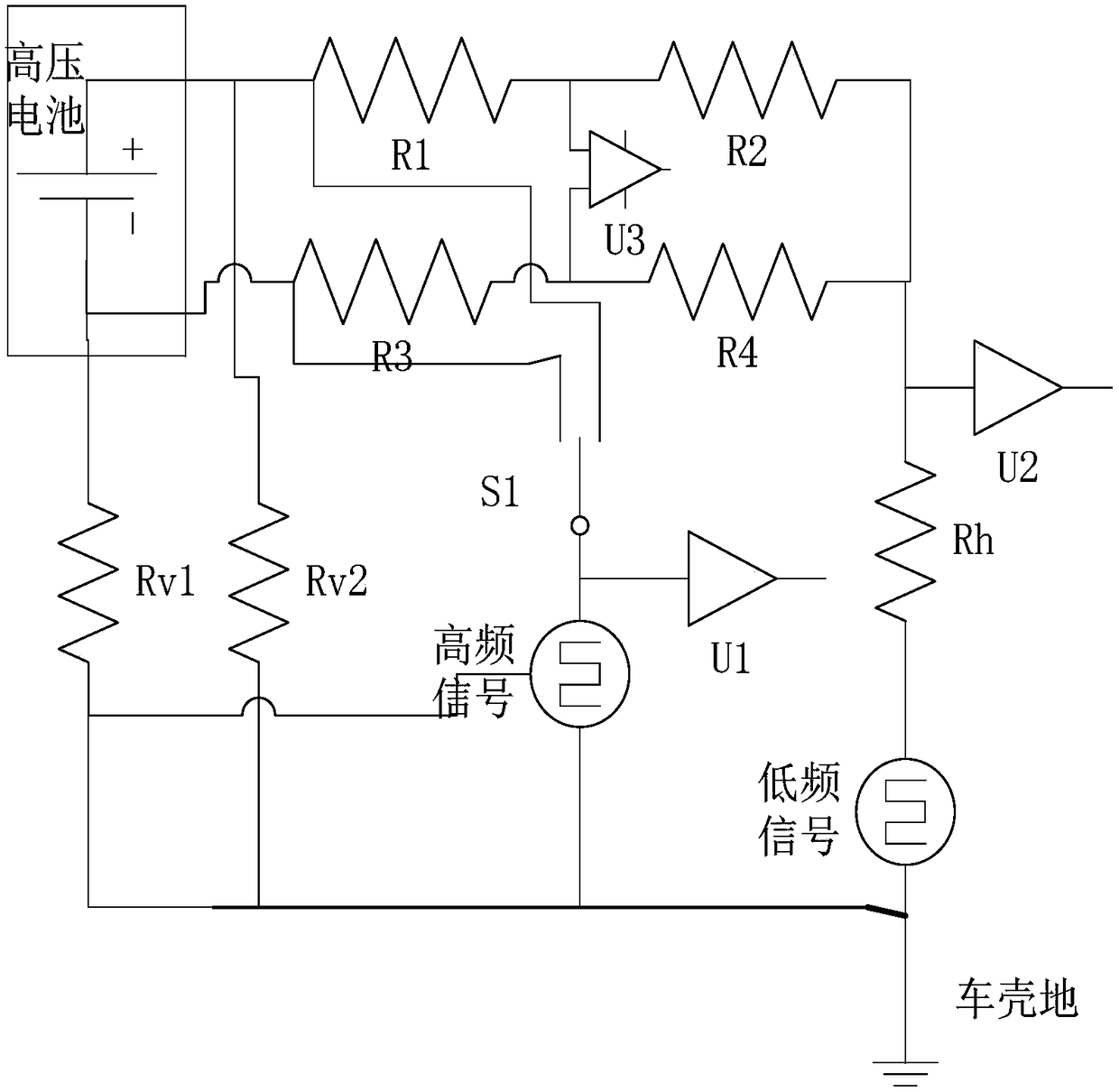
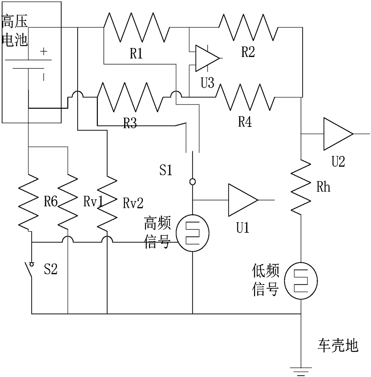
[0034] see figure 1 , is a schematic circuit diagram of an electric vehicle insulation detection device according to an embodiment of the present invention. The electric vehicle insulation detection device includes:

[0035] Low frequency pulse signal generator ( figure 1 medium low frequency signal), high frequency pulse signal generator ( figure 1 High-frequency signal in), the first operational amplifier U1, the second operational amplifier U2, the third operational amplifier U3, the sampling circuit ( figure 1 R1~R4 and Rh in the middle), the two-choice selector switch S1 and the processor unit ( figure 1 not shown). Among them, Rv is the virtual resistance of the high-voltage battery to the car shell, and Rv is the insulation res...


PUM


Abstract

The invention discloses a novel insulation detection device for electric automobiles.The novel insulation detection device for electric automobiles comprises a low-frequency pulse signal generator, a high-frequency pulse signal generator, a first operational amplifier, a second operational amplifier, a third operational amplifier, a one-out-of-two selective switch, a sampling circuit and a processor unit.The sampling circuit comprises a first branch circuit, a second branch circuit and a fifth resistor, wherein the first branch circuit is formed by connecting a first resistor and a second resistor in series, and the second branch circuit is formed by connecting a third resistor and a fourth resistor in series.An input end of the first operational amplifier is connected to the positive pole or negative pole of a high-voltage battery through the selective switch.An input end of the second operational amplifier is connected to the parallel connection point of the first branch circuit and the second branch circuit.An input end of the third operational amplifier is connected to the connection point of the first resistor and the second resistor.The novel insulation detection device for electric automobiles widens the range of insulation detection of electric automobiles and improves the accuracy of insulation detection of electric automobiles.

Description

technical field [0001] The invention relates to the field of new energy vehicle safety detection, in particular to an electric vehicle insulation detection device. Background technique [0002] At present, the common electric vehicle insulation monitoring equipment on the market mainly uses the bus terminal voltage method and the low frequency signal injection method. Patents CN203422422U, CN101158701A, and CN101603986A all disclose a monitoring system for the insulation resistance of high-voltage systems based on the bus terminal voltage method. Insulation resistance value, bus terminal voltage method can calculate the insulation resistance value of the system by measuring the voltage between the DC bus and the electric chassis before and after the standard resistance is incorporated, but the work is relatively unreliable and has high requirements for high-voltage systems (including voltage value, stability, etc.), and cannot respond to the short-to-ground fault inside the...

Claims


Application Information

Patent Timeline
Patent Type & Authority Patents(China)
IPC IPC(8): G01R27/02G01R31/12
CPCG01R27/025G01R31/12
Inventor 戴少洪陈华聪雷学国
Owner FUJIAN WANRUN NEW ENERGY TECH
Learn More