Photoelectric composite cable with special-shaped filling material

A technology of photoelectric composite cable and special-shaped filling rope, which is applied in the field of cables, and can solve problems such as increased cost, difficult recovery, troublesome removal of loose tubes, etc.

Inactive Publication Date: 2016-07-20
蒋菊生
View PDF4 Cites 1 Cited by
  • Summary
  • Abstract
  • Description
  • Claims
  • Application Information

AI Technical Summary

Problems solved by technology

However, the existing photoelectric composite cables mainly have the following problems: (1) When the outer gap between the adjacent conductors is large, in order to make the composite cable round and round, the loose tube that accommodates the optical fiber also needs to be made into a large size. Increased cost; (2) The wire and the loose tube are twisted to form a cable core, and the outside of the cable core is wrapped with a yarn-like substance, which is easy to damage the loose tube, causing abnormal optical signal transmission, and when the temperature changes significantly, the wrapping The substance damages the loose tube, thereby affecting optical communication, and the dressing material itself is expensive; (3) It is not easy to remove the loose tube by twisting the wire and the loose tube, and the dressing material needs to be cut before taking it out. It is easy to damage the cable core, and it is not easy to restore; and it is very troublesome to take out the loose tube

Method used


Image

  • Photoelectric composite cable with special-shaped filling material
  • Photoelectric composite cable with special-shaped filling material
  • Photoelectric composite cable with special-shaped filling material

Examples


Embodiment 1

[0040] Implementation example 1, implementation example 2, and implementation example 3 are embodiments of special-shaped filling ropes in the present invention; implementation example 4 and implementation example 5 are embodiments of photoelectric composite cables with special-shaped filling in the present invention.

[0041] Implementation example 1

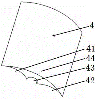
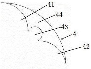
[0042] please see figure 1 figure 2 , optical cable or cable or photoelectric composite cable or photoelectric composite cable with a special-shaped filling rope, which includes a rope body 4, which is characterized in that the rope body is composed of four sections of cylindrical arcs, and the other end of the first cylindrical arc 41 is connected to the third cylinder One end of arc body 43, the other end of the third cylindrical arc body 43 connects one end of second cylindrical arc body 42, one end of fourth cylindrical arc body 44 connects one end of first cylindrical arc body 41, the fourth cylindrical arc body 44 Th...

Embodiment 2

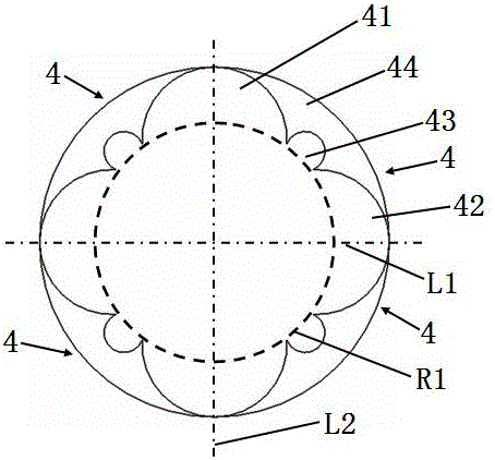
[0046] please see image 3 , and refer to figure 1 with figure 2 The special-shaped filling rope for optical cable or electric cable or photoelectric composite cable or photoelectric composite cable is characterized in that it is formed by splicing successively four small-structure filling rope bodies, and the four small-structure filling rope bodies are assembled into a complete cylinder body surface; the small structure filled rope body includes a rope body 4, and the rope body is composed of four sections of cylindrical arcs, the other end of the first cylindrical arc 41 is connected to one end of the third cylindrical arc 43, and the third cylindrical arc The other end of 43 connects one end of the second cylindrical arc body 42, one end of the fourth cylindrical arc body 44 connects one end of the first cylindrical arc body 41, and the other end of the fourth cylindrical arc body 44 connects the other end of the second cylindrical arc body 42 One end; the bending of th...

Embodiment 3

[0049] please see Figure 4 , and refer to Figure 1 to Figure 3 ; optical cable or electric cable or photoelectric composite cable or photoelectric composite cable with special-shaped filling rope, basically the same as implementation example 2, the difference is that it is formed by one extrusion molding of four small structure filling rope bodies, and the four small structure filling The rope body forms a complete cylinder surface; the small structure filled rope body includes a rope body 4, and the rope body is composed of four sections of cylindrical arcs, and the other end of the first cylindrical arc 41 is connected to the third cylindrical arc 43. One end, the other end of the third cylindrical arc body 43 is connected to one end of the second cylindrical arc body 42, one end of the fourth cylindrical arc body 44 is connected to one end of the first cylindrical arc body 41, and the other end of the fourth cylindrical arc body 44 is connected to the second cylindrical a...


PUM

PropertyMeasurementUnit
melt flow indexaaaaaaaaaa

Abstract

The invention belongs to the technical field of cables, and relates to a photoelectric composite cable with a special-shaped filling material. The cable comprises a reinforcing part, a plurality of power transmission conductors which are located at an outer side of the reinforcing part and sequentially tangential or slightly separated, optical fiber communication units located in gaps outside the adjacent power transmission conductors, a protection layer wrapping the power transmission conductors and the optical fiber communication units, and a sheath layer which covers the protection layer in an extruding manner. The cable is characterized in that the gaps outside the adjacent power transmission conductors are provided with special-shaped ropes; the special-shaped ropes are formed by the sequential jointing or one-time extrusion molding of a plurality of small-structure filling rope bodies; the outer edges of the small-structure filling rope bodies are respectively a complete cylindrical surface; the power transmission conductors respectively consists of a conductor and an insulating body; and the optical fiber communication units respectively consists of an optical fiber and a protection tube wrapping the optical fiber. The special-shaped ropes are made of materials with a special formula. The cable provided by the invention is simple in structure, is lower in cost, is better in performance, and is more convenient in construction.

Description

[0001] This application is a divisional application for an invention patent titled: A photoelectric composite cable with special-shaped filling rope, with an application date of March 31, 2015, and an application number: 201510147109.2; the requirements for an invention patent with an application number: 201510147109.2 The application date is March 10, 2015, the application number is: 201510103917.9, and the application country is China. This divisional application also claims the priority of the original earlier application. technical field [0002] The invention belongs to the technical field of cables, and in particular relates to a photoelectric composite cable with special-shaped filling and a manufacturing method thereof. Background technique [0003] With the rapid development of the communication industry, the application of optical fiber cables and wires and cables is increasing. The use of photoelectric composite cables can make electricity and light directly enter...

Claims


Application Information

Patent Timeline
Patent Type & Authority Applications(China)
IPC IPC(8): H01B9/00H01B7/17H01B7/18G02B6/44
CPCG02B6/44G02B6/4407G02B6/4416G02B6/443G02B6/4432H01B7/04H01B7/17H01B7/18H01B7/1875H01B7/1895H01B7/28H01B7/282H01B7/361H01B9/00H01B9/005H01B11/22H01B13/00H01B13/221
Inventor 蒋菊生
Owner 蒋菊生
Why Eureka
Try Eureka