Buck type single-stage LED drive circuit of unity power factor

A unit power factor, LED drive technology, applied in the direction of output power conversion devices, electric light sources, electrical components, etc., can solve the problems of input current dead zone, THD, large input current, etc., to eliminate dead zone, simple design, Reduce the effect of THD

Inactive Publication Date: 2016-07-20
FUZHOU UNIVERSITY
View PDF3 Cites 7 Cited by
  • Summary
  • Abstract
  • Description
  • Claims
  • Application Information

AI Technical Summary

Problems solved by technology

[0006] The purpose of the present invention is to provide a step-down LED constant current drive circuit with unit power factor to solve the problem of large input current THD caused by the input current dead zone of the step-down PFC circuit

Method used


Image

  • Buck type single-stage LED drive circuit of unity power factor
  • Buck type single-stage LED drive circuit of unity power factor
  • Buck type single-stage LED drive circuit of unity power factor

Examples


Embodiment Construction

[0025] The technical solution of the present invention will be described in detail below in conjunction with the drawings.

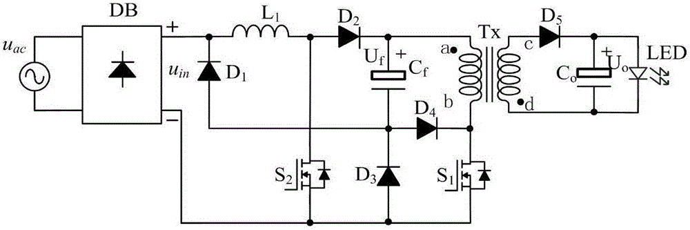
[0026] The invention provides a step-down single-stage LED drive circuit with unit power factor, such as figure 1 Shown, including: single-phase AC input power u ac , Single-phase rectifier bridge DB, power switch tube S 1 , Power switch S 2 , Diode D 1 , Diode D 2 , Diode D 3 , Diode D 4 , Diode D 5 , Inductance L 1 , Output filter capacitor C o , Bus capacitance C f , High frequency transformer T x And LED light load; AC input power u ac The two input phase voltages of the rectifier bridge DB are respectively connected to the two AC input terminals; the DC side positive output terminal of the single-phase rectifier bridge DB is respectively connected to the diode D 1 Cathode and inductance L 1 One end of the single-phase rectifier bridge DB is connected to the negative output end of the DC side of the power switch S 1 Source, power switch S 2 Source and dio...


PUM


Abstract

The present invention relates to a buck type single-stage LED drive circuit of a unity power factor, and discloses the buck type single-stage LED drive circuit of wide input voltage range and low THD and unity power factor. A forestage circuit adopts a time division multiplexing buck circuit and a buck-boost circuit to be integrated with a back-stage flyback convertor, so that an inherent dead zone of a conventional buck type PFC circuit AC input current is eliminated, and accordingly, the THD of the input current is reduced. By the staged working, the circuit can work in a buck mode and also can work in a buck-boost mode. A buck-boost switching tube works when an input voltage is less than an output voltage, so that the conduction dead zones can be reduced. Meanwhile, two switching tubes in the circuit are in common ground, so that the design of a driving control circuit is simpler, and the unity power factor is realized.

Description

Technical field [0001] The invention relates to a high power factor, low THD AC-DC switch conversion LED drive circuit, in particular to a unit power factor step-down LED constant current drive circuit. Background technique [0002] In recent decades, power electronic technology has been rapidly developed, and the application range of power electronic devices has become increasingly extensive, covering almost all electric energy applications from power generation, transmission, distribution to electricity consumption. However, as more and more power electronic devices are connected between the power grid and user equipment, various harmonics generated by switching power supplies have caused pollution to the power grid. If the harmonics are not processed, it may cause interference between power grid equipment, communication system disorder, electrical malfunction, power system overheating and cause fires. The issue of harmonic control has been paid more and more attention by gove...

Claims


Application Information

Patent Timeline
IPC IPC(8): H05B33/08H02M1/12H02M1/42H05B44/00
CPCH02M1/12H02M1/425H05B45/37Y02B70/10
Inventor 林维明刘贤庆
Owner FUZHOU UNIVERSITY
Why Eureka
Try Eureka