Eureka AIR delivers breakthrough ideas for toughest innovation challenges, trusted by R&D personnel around the world.

Manufacturing method of individual hip joint percutaneous puncture guide plate

A production method and hip joint technology, applied in the field of medical devices, can solve the problems of low puncture success rate, increased radiation dose, and easy nerve damage, etc., and achieve the effects of reduced operation time, fast response, and low cost of personalization

Inactive Publication Date: 2016-07-27
GUIZHOU NORMAL UNIVERSITY +1
View PDF3 Cites 9 Cited by
  • Summary
  • Abstract
  • Description
  • Claims
  • Application Information

AI Technical Summary

Problems solved by technology

The empirical method is the anterior approach, that is, at the midpoint of the line connecting the anterior superior iliac spine and the pubic tubercle, 2 cm below the inguinal ligament, and the needle is inserted vertically outside the femoral artery. This method is based on the subjective experience of the doctor. difference, the puncture success rate is low, and it is easy to cause nerve damage; C-arm X-ray fluoroscopy-assisted puncture can adjust the direction of needle insertion, which has the advantages of accurate positioning and easy operation, but the amount of radiation received by the patient increases during the operation; ultrasound-assisted puncture It can dynamically and accurately monitor the positional relationship between the puncture needle and the joint cavity and its surrounding important structures in real time, and ultrasound technology is a safe and convenient tool, but the combination of ultrasound to adjust the direction of the needle will cause the patient to undergo multiple punctures

Method used


Image

  • Manufacturing method of individual hip joint percutaneous puncture guide plate

Examples


Embodiment Construction

[0024] Hereinafter, preferred embodiments of the present invention will be described in detail with reference to the accompanying drawings. It should be understood that the preferred embodiments are only for illustrating the present invention, but not for limiting the protection scope of the present invention.

[0025] A method for making a personalized hip joint percutaneous puncture guide, comprising the steps of:

[0026] 1) Establishment of 3D geometric model: Obtain thin-layer scan data of the patient's hip joint, import it into medical modeling software in DICOM format, and generate visualized 3D models of bones, soft tissues, skin, and important blood vessels through morphological processing, and store them in stl Format export and save;

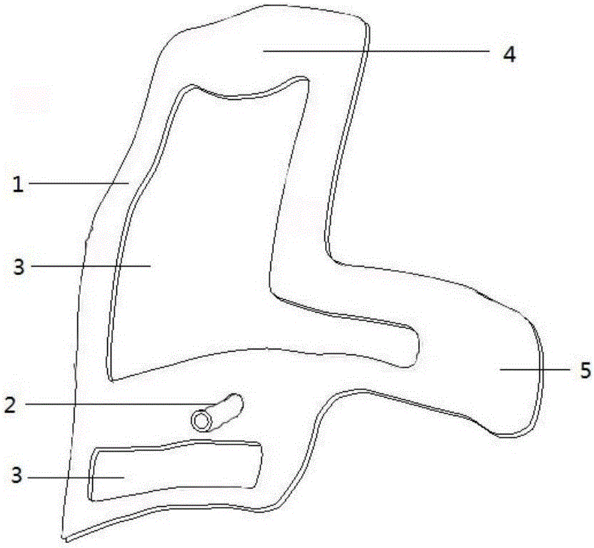
[0027] 2) Determine the puncture channel 2 (such as figure 1 shown): In the medical modeling software, determine the puncture target point, needle insertion direction and angle, extract the shape of the puncture needle, and fit it i...


PUM


Abstract

The invention discloses a manufacturing method of an individual hip joint percutaneous puncture guide plate. The manufacturing method comprises the following steps that 1, a three-dimensional geometric model is built, wherein thin-layer chromatographic scanning data of the hip joint of a patient is obtained, and three-dimensional models of skeleton, soft tissue, skin and important blood vessels are built and exported and stored in a stl format; 2, a puncture channel is determined, wherein in modeling software, a puncture target point and the needle entering direction and angle are determined, the puncturing needle form is extracted, a puncture channel is formed through fitting, and then the puncture channel is reversely prolonged to puncture out of skin to form a body surface marker to be exported and stored in an stl format; 3, the guide plate is designed, wherein in software, mesh optimization is carried out on the three-dimensional models of skeleton, soft tissue, skin and important blood vessels, a skin surface mesh is extracted, reverse offset thickening is performed to form a guide plate panel, a bone mark is marked, and the guide plate panel is in fit with the reverse puncture channel to obtain a guide plate model; 4, a guide plate entity is obtained through 3D printing. The manufacturing method has the advantages of being individual, accurate, rapid, low in cost and efficient.

Description

technical field [0001] The invention relates to the technical field of medical devices, in particular to a method for manufacturing a personalized hip joint percutaneous puncture guide. Background technique [0002] The hip joint has a relatively stable bony structure and is one of the main weight-bearing joints of the human body. There are many important structures around it. Hip joint diseases such as spondylitis hip arthritis can cause pain and dysfunction of the hip joint, and the progressive aggravation of the disease will seriously affect the quality of life of the patient and cause a high disability rate. For patients with hip joint diseases who do not need or cannot tolerate surgery in the early and middle stages, clinically, hip joint puncture fluid testing, drug injection treatment, and bone biopsy around the hip joint are currently important means of diagnosis and treatment. This type of technique requires accurate puncture of the joint cavity, and it is necessar...

Claims


Application Information

Patent Timeline
IPC IPC(8): A61B17/34B33Y50/00B33Y10/00
CPCA61B17/3403A61B2017/3405B33Y10/00B33Y50/00
Inventor 伍权孙立徐卫平田晓滨胡圣波汤耿刘腾
Owner GUIZHOU NORMAL UNIVERSITY
Why Eureka
Eureka Blog
Learn More