Multi-laser-head laser cutting machine

A laser cutting machine and multi-laser technology, applied in laser welding equipment, welding equipment, metal processing equipment, etc., can solve problems such as increased procurement, increased labor costs and material costs, and inability to complete complex forming and cutting requirements, so as to improve finished products Quality, the effect of reducing labor and material costs

Active Publication Date: 2016-07-27
GUANGZHOU GREAT YEAR LASER TECH CO LTD
View PDF9 Cites 34 Cited by
  • Summary
  • Abstract
  • Description
  • Claims
  • Application Information

AI Technical Summary

Problems solved by technology

[0002] In the past, fiber laser cutting machines could not cut composite materials (metal and non-metal composites). There was a layer of plastic protective film on the surface of stainless steel plates. When fiber laser cutting stainless steel plates, the upper layer was torn off first. The protective film is cut, and after the cutting is completed, a layer of plastic film is required to protect the finished or semi-finished product from scratches, and scratches will also occur during the second peritoneum, so the labor cost and material cost are greatly increased. At the same time, it also causes the quality of finished products or semi-finished products to decline after cutting; in addition, the cutting of aluminum composite boards and PCB boards adopts cutting processing technology, which cannot complete complex forming and cutting below 20mmx20mm, and the cutting processing technology must clamp materials It can only be completed (the clamping position must be reserved when clamping the material), so the labor cost and material cost are increased, and the complex forming and cutting requirements below 20mmx20mm cannot be completed;
[0003] When the customer uses the laser cutting machine to complete the material processing of a single different material (metal material: iron plate, aluminum plate, non-metallic material acrylic plate, PVC plate, MDF, wood plate), the following two options are adopted: 1. Purchase a medium and large High-power carbon dioxide (Co2) laser cutting machine; this solution has high equipment cost and high later use cost (higher electricity cost and auxiliary gas cost); 2. Purchase a fiber laser to cut metal materials, purchase a Carbon dioxide (Co2) laser cutting machine cuts non-metallic materials; therefore, the cost of purchase and use is greatly increased (two devices occupy more space for placement)

Method used


Image

  • Multi-laser-head laser cutting machine
  • Multi-laser-head laser cutting machine
  • Multi-laser-head laser cutting machine

Examples


Embodiment 1

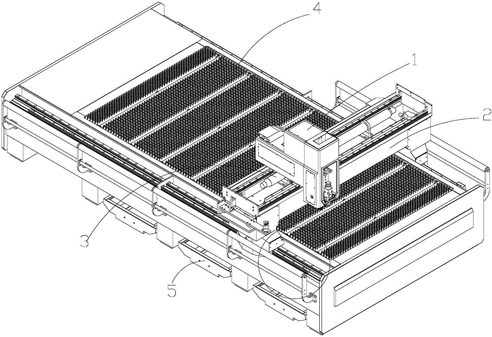
[0036] Such as figure 1 The mixed light source laser cutting machine shown includes a worktable 4, a number of waste discharging devices 5 are arranged at the lower part of the worktable, and a beam device 2 that moves back and forth relative to the worktable is installed above the worktable, and a laser tube is installed inside the beam device 2 3. The beam device 2 is also installed with a multi-laser head cutting assembly 1 that moves left and right relative to the beam device. The light beam emitted by the laser tube 3 is reflected by the reflection structure and transmitted to the multi-laser head cutting assembly 1, inside the multi-laser head cutting assembly 1. It includes a carbon dioxide laser device and at least one non-carbon dioxide laser laser device.

[0037] The laser tube emits a carbon dioxide laser radio frequency tube light source, and the non-carbon dioxide laser laser device is a fiber laser light source device.

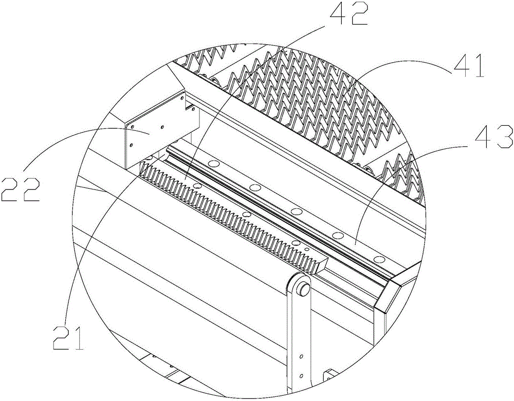
[0038] Such as figure 2 As shown, the upper s...

Embodiment 2

[0048] A multi-laser laser cutting machine with the same structure as the multi-laser laser cutting machine in Example 1, wherein the laser tube emits a carbon dioxide laser radio frequency tube light source, and the non-carbon dioxide laser laser device is a solid-state (YAG) laser light source device.

Embodiment 3

[0050] The multi-laser-head laser cutting machine in embodiment 1 is a multi-laser-head laser cutting machine with the same structure, wherein the laser tube emits a carbon dioxide laser tube light source, and the non-carbon dioxide laser laser device is a semiconductor laser light source device.


PUM


Abstract

The invention provides a multi-laser-head laser cutting machine. The multi-laser-head laser cutting machine comprises a workbench, a laser cutting control system, a CO2 laser generator, a CO2 laser power supply, a CO2 laser reflector, at least one non-CO2 laser generator, for example, a fiber laser generator, a multi-laser-head cutting assembly, an X-axis movement assembly, a Y-axis movement assembly, a Z-axis movement assembly, a laser generator cooling system, an object carrying working table, a cutter console, a waste material collecting device and a dust collecting exhaust fan. Two or more than two laser sources are combined on the same laser cutting equipment by the multi-laser-head cutting assembly, so that the cutting processing of composites and the cutting processing of different single materials are realized.

Description

Technical field [0001] The invention relates to the field of laser cutting, in particular to a multi-laser head laser cutting machine. Background technique [0002] In the past, the fiber laser cutting machine could not cut composite materials (metal and non-metal composite). There was a protective film on the surface of the stainless steel plate. When the fiber laser cuts the stainless steel plate, the upper layer must be removed first. The protective film is cut. After the cutting is completed, a layer of plastic film is required to protect the finished or semi-finished product from scratching. Scratching will also occur during the secondary peritoneum, which greatly increases the labor cost and material cost. At the same time, the quality of the finished or semi-finished products after cutting is reduced; in addition, cutting aluminum and PCB boards are made by cutting processing technology. The cutting processing technology cannot complete the complex forming cutting below 20...

Claims


Application Information

Patent Timeline
Patent Type & Authority Applications(China)
IPC IPC(8): B23K26/38B23K26/70B23K26/142
CPCB23K26/142B23K26/38B23K26/702B23K26/703
Inventor 刘继德
Owner GUANGZHOU GREAT YEAR LASER TECH CO LTD
Why Eureka
Try Eureka