Oil pressure assistance braking system and control method thereof

A technology of a braking system and a control method, which is applied to the control of the above-mentioned braking system and the field of hydraulic power-assisted braking system, can solve problems such as power consumption and noise, and achieve fast adjustment response, compact system structure and low cost. Effect

Active Publication Date: 2016-07-27
WUHU BETHEL AUTOMOTIVE SAFETY SYST
View PDF6 Cites 22 Cited by
  • Summary
  • Abstract
  • Description
  • Claims
  • Application Information

AI Technical Summary

Problems solved by technology

It is mainly reflected in two aspects: one is the development of new energy vehicles, such as the development of electric vehicles, so that there is no vacuuming power source for the vacuum booster on the vehicle-the engine, an electronic vacuum pump must be connected externally, and its disadvantage is th...

Method used


Image

  • Oil pressure assistance braking system and control method thereof
  • Oil pressure assistance braking system and control method thereof
  • Oil pressure assistance braking system and control method thereof

Examples


specific Embodiment approach

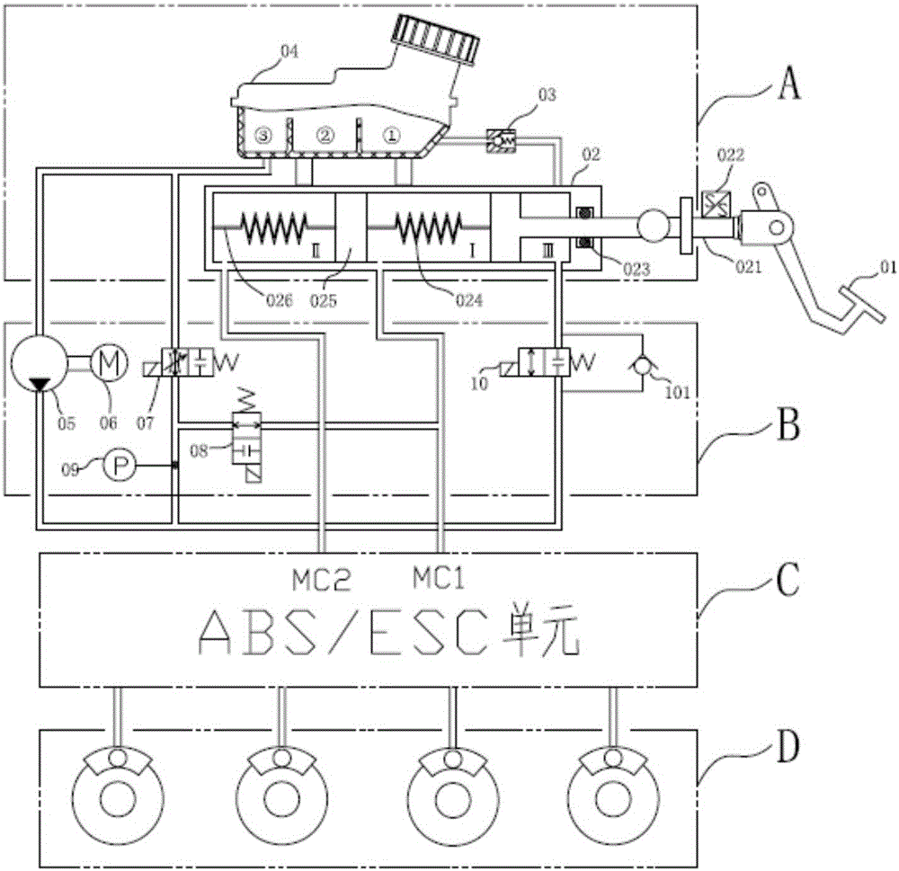
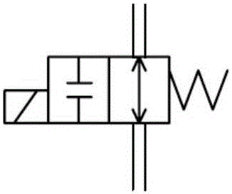
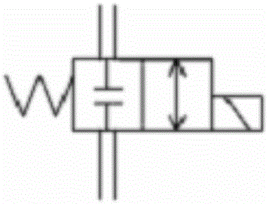
[0125] The pressure sensor 09 transmits the signal to the electronic control unit, and the electronic control unit controls the normally open solenoid valve 08 to be energized and closed, which cuts off the connection between the boost source and the leakage chamber, and drives the hydraulic pump 05 and the motor 06 to work at the same time, and the brake hydraulic pressure is normally closed. The solenoid valve 10 flows into the chamber III of the brake master cylinder 02, and pushes the pedal piston rod 021 to move forward to realize power boosting.

[0126] 7. Figure 15 It is a schematic diagram of the relationship curve between the brake hydraulic pressure P and the pedal stroke S of the hydraulic power assist system of the present invention.

[0127] In the present invention, the electronic control unit drives the hydraulic pump 05 and the motor 06 to pressurize the system, and at the same time controls the valve opening of the pressure regulating valve 07 to adjust the ...

Embodiment approach

[0128] 8. The stepped structure of the piston rod of the piston in the master cylinder makes the hydraulic booster system of the present invention not need to add a pedal simulation device, and can also achieve a good pedal feeling. The specific implementation method is:

[0129] The pressure difference formed by the pedal piston rod 021 in the piston bore area ratio of the first chamber and the third chamber of the brake master cylinder 02 is used as the driver's pedal feeling. According to the needs of customers, an appropriate piston-to-bore ratio can be designed to achieve the required boost ratio.

[0130] Five, the expansion technical scheme of the present invention:

[0131] The above-mentioned content has expressed the working principle and the hydraulic circuit of the present invention's scheme completely, and the present invention has done following expansion on the basis of this scheme:

[0132] Such as Figure 16 As shown, a high-pressure accumulator 11 is provi...


PUM


Abstract

The invention discloses an oil pressure assistance braking system.A braking main cylinder (02) is sequentially provided with a cavity II, a cavity I and a cavity III in the direction from a piston to a piston rod.The cavity III is an oil cavity where the piston rod is located.The cavity I and the cavity II are connected with an MC port of an ABS/ESC unit (C).An electronic control assistance unit (B) is provided with three electromagnetic valves, a pressure sensor and a one-way valve, wherein the electromagnetic valves are a normally-closed pressure regulating valve, a normally-opened electromagnetic valve and a normally-closed electromagnetic valve, and the normally-closed pressure regulating valve is connected with an oil can.By the adoption of the technical scheme, the production cost is reduced, and the size is smaller, which is beneficial for installation and arrangement on a vehicle; pressure can be increased, reduced and regulated fast, the adjusting response is fast, and the response requirement for a motor-hydraulic pump system and the requirement for a motor and ECU power are far lower than that of the scheme in which the motor is required to rotate forward and backward fast.A vacuum booster is omitted, the system is more compact in structure, and the cost of the whole braking system is low.

Description

technical field [0001] The invention belongs to the technical field of automobile brake systems. More specifically, the present invention relates to hydraulically assisted braking systems. In addition, the present invention also relates to a control method of the above braking system. Background technique [0002] The boost of the traditional automobile braking system is to use the vacuum generated by the engine or the vacuum generated by the electronic vacuum pump to realize the brake pressure build-up in the vacuum booster. like Figure 17 Shown, serial number 4 is described vacuum booster. When the driver brakes, the brake pedal 6 is stepped on, and the brake master cylinder 3 is driven to pass through the electronically controlled pressure regulating unit ABS / ESC2 to build up pressure on the brake 1 to generate brake fluid pressure; a vacuum booster is needed for the pedal during this process. The force is proportionally amplified, so that the driver can achieve the b...

Claims


Application Information

Patent Timeline
IPC IPC(8): B60T13/12B60T13/14B60T13/68
CPCB60T13/12B60T13/146B60T13/686
Inventor 袁永彬徐文泉张平平黄先明
Owner WUHU BETHEL AUTOMOTIVE SAFETY SYST
Why Eureka
Try Eureka