
Process of integrally winding foil coils with low-voltage windings of axially split transformers

A technology for splitting transformers and low-voltage windings, applied in the field of transformers, can solve the problems of affecting the short-circuit resistance of coils, wasting man-hours and materials, and poor oil flow channels, so as to save assembly time, reduce unbalance rate, and smooth oil flow Effect

Active Publication Date: 2017-06-27
ZHENLAI XINYUAN COMPOSITE MATERIAL TECH
View PDF6 Cites 0 Cited by
  • Summary
  • Abstract
  • Description
  • Claims
  • Application Information

AI Technical Summary

Problems solved by technology

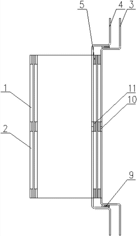
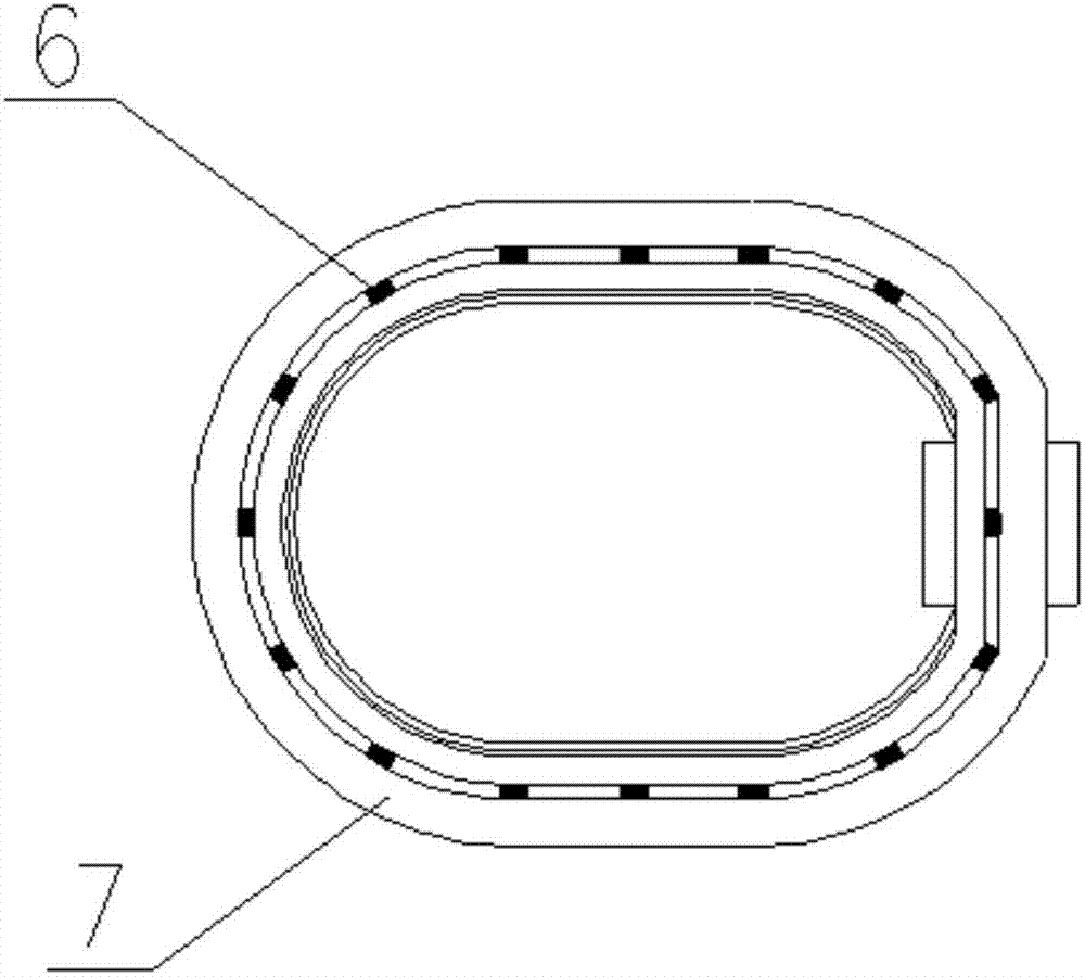
[0005] The technical problem to be solved by the present invention is to provide an axially split transformer low-voltage winding integrally wound foil coil structure and process, which is used to solve the waste of man-hours and materials of the traditional low-voltage split coil; the oil flow channel is not smooth, which affects the temperature rise ; Winding size deviation, affecting the short-circuit resistance of the coil and other technical issues

Method used


Image

  • Process of integrally winding foil coils with low-voltage windings of axially split transformers
  • Process of integrally winding foil coils with low-voltage windings of axially split transformers
  • Process of integrally winding foil coils with low-voltage windings of axially split transformers

Examples


Embodiment 1

[0082] Embodiment 1. The process of axially splitting the low-voltage winding of the transformer to integrally wind the foil coil is characterized in that it includes the following steps

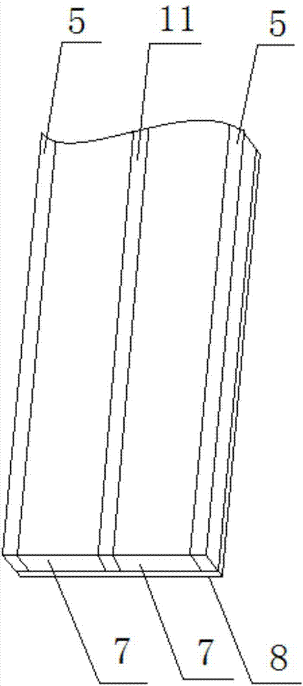
[0083] Step 1. According to the requirements of the drawings, select the same two shafts of metal foil and one shaft of insulating paper 8, where the width of insulating paper 8 is 30mm larger than the sum of the widths of the two shafts of metal foil;

[0084] Step 2. Hang the two-axis metal foil on the wire reel shelf of the double-layer foil winding machine at the same time, put the insulating paper 8 on the wire reel shelf, and pull the starting end of the two-axis metal foil and the starting end of the insulating paper 8. From the beginning to the worktable, the starting edge of the two-axis metal foil and the starting edge of the insulating paper 8 are on the same straight line, and the two-axis metal foil is symmetrically laid on the upper surface of the insulating paper 8, and the gap...

Embodiment 2

[0104] Embodiment 2, the process of axially splitting the low-voltage winding of the transformer to integrally wind the foil coil, is characterized in that it includes the following steps

[0105] Step 1. According to the requirements of the drawings, select the same two shafts of metal foil and one shaft of insulating paper 8, where the width of insulating paper 8 is 40mm larger than the sum of the widths of the two shafts of metal foil;

[0106] Step 2. Hang the two-axis metal foil on the wire reel shelf of the double-layer foil winding machine at the same time, put the insulating paper 8 on the wire reel shelf, and pull the starting end of the two-axis metal foil and the starting end of the insulating paper 8. From the beginning to the worktable, the starting edge of the two-axis metal foil and the starting edge of the insulating paper 8 are on the same straight line, and the two-axis metal foil is symmetrically laid on the upper surface of the insulating paper 8, and the ga...

Embodiment 3

[0126] Embodiment 3, the process of axially splitting the low-voltage winding of the transformer to integrally wind the foil coil is characterized in that it includes the following steps

[0127] Step 1. According to the requirements of the drawings, select the same two shafts of metal foil and one shaft of insulating paper 8, where the width of insulating paper 8 is 45mm larger than the sum of the widths of the two shafts of metal foil;

[0128]Step 2. Hang the two-axis metal foil on the wire reel shelf of the double-layer foil winding machine at the same time, put the insulating paper 8 on the wire reel shelf, and pull the starting end of the two-axis metal foil and the starting end of the insulating paper 8. From the beginning to the worktable, the starting edge of the two-axis metal foil and the starting edge of the insulating paper 8 are on the same straight line, and the two-axis metal foil is symmetrically laid on the upper surface of the insulating paper 8, and the gap ...


PUM

PropertyMeasurementUnit
widthaaaaaaaaaa
thicknessaaaaaaaaaa

Abstract

The present invention provides a structure and process of an integrally wound foil coil of a low voltage winding of an axial split transformer. The metal foil winding in the present invention is made of copper foil or aluminum foil, and is made by using a two-layer foil winding machine to perform coaxial winding. A middle insulation annular pad is made of cardboard, an insulation distance is reduced to 10 mm to 15 mm, and the consumption of a silicon steel sheet and an insulation material is reduced by 1.2% to 1.5%. A heat dissipation oil passage is of a vertical long structure, a support strip is axially parallel to the oil passage, and end rings are saved, so that it is ensured that oil flow is smooth. In a semi-traversal running state, when one split coil is impacted by short-circuit power, another split coil may be mechanically linked to the short-circuited coil by the long oil passage support strip, so that anti-short circuit strength is improved. The number of low-voltage coils of each transformer that are subjected to winding and sleeving is decreased from the number, 6, of traditional coils made by winding a flat wire to 3, so that working hours of winding and sleeving of low-voltage coils are reduced by 50%, and working efficiency and produce performance are improved.

Description

technical field [0001] The invention belongs to the technical field of transformers, and in particular relates to an axial split transformer low-voltage winding integrally wound foil-type coil structure and process with a voltage level of 35 kV and below. Background technique [0002] In the power system, low-voltage split transformers are usually used for factory transformers and start-up transformers. Since the beginning of the 21st century, with the increase of installed capacity of photovoltaic power generation in my country, many new photovoltaic power plants have widely used low-voltage split transformers in order to save capital construction investment. Compared with the general power transformer, the low-voltage split transformer has many differences. It consists of a parallel high-voltage winding and several axially or radially split low-voltage windings. The normal power transmission of the split transformer is only between the high-voltage and low-voltage windings...

Claims


Application Information

Patent Timeline
Patent Type & Authority Patents(China)
IPC IPC(8): H01F27/28H01F27/30H01F27/12H01F41/061H01F41/12
CPCH01F27/12H01F27/2847H01F27/2876H01F27/306H01F41/122H01F2027/2857
Inventor 王喜权颜伟嘉李丰田赵亮王刚张磊梁谦诚
Owner ZHENLAI XINYUAN COMPOSITE MATERIAL TECH
Learn More