Seawater desalination system with waste heat recovery device

A waste heat recovery device, seawater technology, applied in seawater treatment, water/sewage treatment, general water supply conservation, etc., can solve problems such as large power consumption, large energy consumption, waste, etc. The effect of reducing the burden

Inactive Publication Date: 2016-08-03
SHANGHAI JIAOYING ENERGY TECH
View PDF4 Cites 5 Cited by
  • Summary
  • Abstract
  • Description
  • Claims
  • Application Information

AI Technical Summary

Problems solved by technology

[0002] The bottleneck of seawater desalination technology driven by thermal method is the large energy consumption, mainly manifested in the need to consume a lot of electricity to heat the seawater to be evaporated, so as to generate enough steam to condense into fresh water
As we all know, before a large amount of evaporation, the temperature of seawater must be greatly increased. However, water is a substance with a large specific heat capacity. If you rely solely on external heat sources to increase the temperature of seawater, it will inevitably consume a lot of energy.
On the other hand, the boiling seawater in the evaporator gradually turns into concentrated brine, which needs to be discharged. The concentrated brine must have a higher temperature when discharged. If the heat energy carried by the concentrated brine is allowed to dissipate, it is also a waste. , at the same time, the discharge of high-temperature concentrated brine to the sea area will inevitably affect the ecological environment of the nearby sea area

Method used


Image

  • Seawater desalination system with waste heat recovery device

Examples


Embodiment Construction

[0024] The following will clearly and completely describe the technical solutions in the embodiments of the present invention with reference to the accompanying drawings in the embodiments of the present invention. Obviously, the described embodiments are only some, not all, embodiments of the present invention. Based on the embodiments of the present invention, all other embodiments obtained by persons of ordinary skill in the art without creative efforts fall within the protection scope of the present invention.

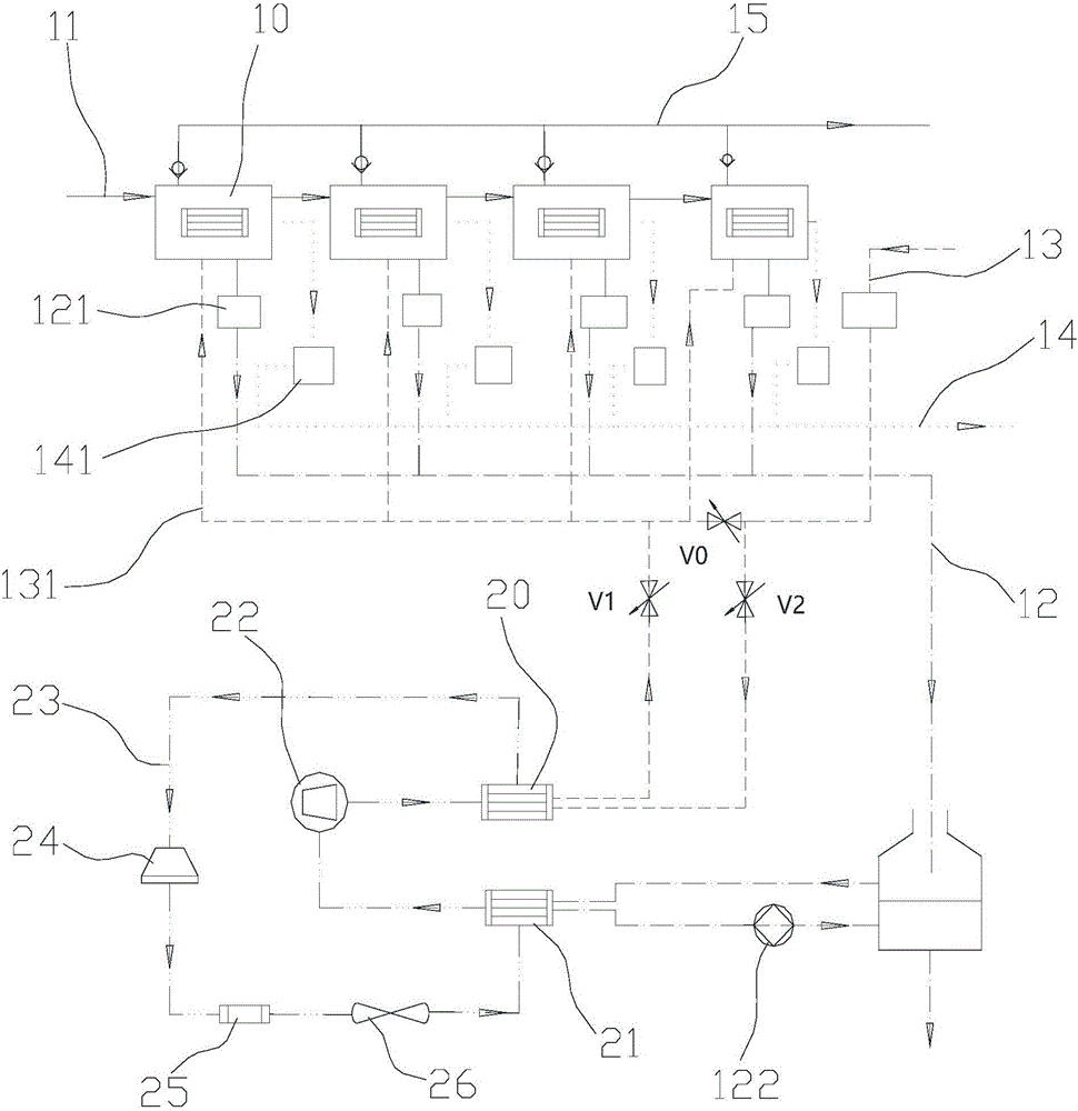
[0025] Such as figure 1 As shown, the seawater desalination system with waste heat recovery device according to the present invention includes:

[0026] The effect chamber evaporator 10 has a plurality of effect chambers distributed sequentially from top to bottom, for heating and spraying seawater and generating concentrated brine and steam;

[0027] The heat source 11 is used to heat the seawater sprayed on the effect chamber evaporator 10 for the first time;

...


PUM


Abstract

Provided is a seawater desalination system with a waste heat recovery device .The seawater desalination system comprises effect chamber evaporators, a heat source, a seawater pipeline, a fresh water pipeline and a strong brine pipeline; a heat pump system comprises a heat transfer working medium fluid pipeline, a heat transfer heat pump compressor, a heat pump condenser and a heat pump evaporator, the two ends of the heat transfer working medium fluid pipeline are connected to the input end and the output end of the heat pump compressor respectively, the heat pump condenser is installed on the side, close to the input end of the heat pump compressor, of the working medium fluid pipeline, the heat pump evaporator is installed on the side, close to the output end of the heat pump compressor, of the working medium fluid pipeline, the section, located in the heat pump condenser, of a seawater pipeline is a seawater pipe coil, and the section, located on the heat pump evaporator, of the strong brine pipeline is a strong brine pipe coil .According to the seawater desalination system with the waste heat recovery device, heat energy in high-temperature strong brine to be discharged is utilized, heating is conducted on seawater to be evaporated through the heat pump system, the initial temperature of seawater is increased, a burden of the heat source is reduced, and meanwhile the influence of emissions to the adjacent sea areas is reduced.

Description

technical field [0001] The invention relates to seawater desalination equipment, in particular to a seawater desalination system with a waste heat recovery device. technical background [0002] The bottleneck of seawater desalination technology driven by thermal methods lies in the large energy consumption, which is mainly manifested in the need to consume a large amount of electric energy to heat the seawater to be evaporated, so as to generate enough steam to condense into fresh water. As we all know, the temperature of seawater must be greatly increased before a large amount of evaporation occurs. However, water is a substance with a large specific heat capacity. If you rely solely on external heat sources to increase the temperature of seawater, it will inevitably consume a lot of energy. On the other hand, the boiling seawater in the evaporator gradually turns into concentrated brine, which needs to be discharged. The concentrated brine must have a higher temperature wh...

Claims


Application Information

Patent Timeline
Patent Type & Authority Applications(China)
IPC IPC(8): C02F1/12C02F1/16C02F103/08
CPCC02F1/12C02F1/16C02F2103/08Y02A20/124
Inventor 彭志刚别如山韩延民彭达
Owner SHANGHAI JIAOYING ENERGY TECH
Why Eureka
Try Eureka