Laser level gauge and application of laser level gauge in installation of bridge stand

A laser level, laser level technology, applied in instruments, measuring devices, measuring instruments and other directions, can solve the problems of low efficiency, low precision, inconvenient use, etc., to save installation and construction time, improve work efficiency, and reduce engineering costs. Effect

Inactive Publication Date: 2016-08-03
MCC5 GROUP CORP SHANGHAI
View PDF7 Cites 2 Cited by
  • Summary
  • Abstract
  • Description
  • Claims
  • Application Information

AI Technical Summary

Problems solved by technology

Although this improved laser level can be used in construction to generate a light plane for the datum of construction projects, it uses a pendulum structure, which makes the entire laser level complex, inconvenient to use, and poor intuition, which affects the use effect
In the bridge project, the precision of the bridge installation is high: the verticality of the column is ≤2‰, the height deviation of the pallet on the same straight line is ≤±5mm, and the accuracy control is difficult
The traditional construction method uses the reference line to control the vertical deviation of the supporting arms of the row of bridges, and the verticality of the columns of the bridge with a hammer, which has low precision, low efficiency, and high labor intensity for workers.
[0003] Therefore there is above-mentioned inconvenience and problem in the method for known bridge frame installation

Method used


Image

  • Laser level gauge and application of laser level gauge in installation of bridge stand
  • Laser level gauge and application of laser level gauge in installation of bridge stand
  • Laser level gauge and application of laser level gauge in installation of bridge stand

Examples


Embodiment 1

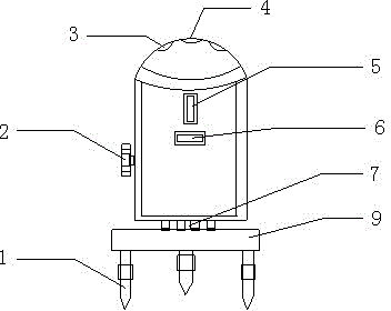
[0029] see now figure 1 , figure 1 It is a schematic structural diagram of a laser level in an embodiment of the present invention. As shown in the figure, the base is a disc, and the bottom of the disc is provided with three telescopic legs 1 for adjusting the levelness and height of the laser level;

[0030] The upper part of the cylinder body is provided with a dome cover, a level 4 is provided at the top of the dome cover, and a fine-tuning button 3 is provided in the middle of the dome cover; four laser emitters 15 are arranged in the cylinder body, and the four laser emitters are arranged on the same plane. Arranged in a cross shape with each other, each laser emitter is provided with a laser vertical line emission window and a laser horizontal line emission window on the corresponding cylinder circumference, and the fine-tuning button 3 is connected with the electronic system built in the emitter to adjust the output of the laser emitter. The direction and angle of th...

Embodiment 2

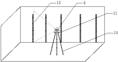
[0035] see now image 3 and Figure 4 , image 3 It is a schematic diagram of using a laser level to control the installation of bridge columns in an embodiment of the present invention, Figure 4 It is a schematic diagram of using a laser level to control the installation of a bridge support arm according to an embodiment of the present invention.

[0036] The method of using the laser level of the present invention in the installation of the bridge support arm is as follows:

[0037] 1. Place the laser level on a tripod, or on a stable plane, and place it next to the bridge to be installed, and adjust the three legs on the base to make the instrument bubble in the line.

[0038] 2. When the circular level bubble is centered and the laser level is leveled, turn the switch knob clockwise to turn on the instrument. At the same time, the transmitters on the four sides emit laser beams. The laser beams on each side are composed of vertical and horizontal linear laser beams. V...


PUM


Abstract

The invention relates to a laser level gauge. The laser level gauge comprises a pedestal and a cylindrical shell, and is characterized in that the pedestal is a disc, three telescopic supporting legs (1) are arranged at the bottom of the disc; a circular arch top cover is arranged at the upper part of the cylindrical shell, a level meter (4) is arranged at the top of the circular arch top cover, a spin button is arranged at the central part of the circular arch top cover; four laser emitters (15) are arranged in the cylindrical shell, and a laser vertical line emission window and a laser horizontal line emission window are arranged on each laser emitter at corresponding circumference of the cylindrical shell. The laser level gauge has the advantages of simple structure, and convenient carrying and usage, is suitable for various work environment, and can effectively increase the installation precision of the bridge stand; the horizontal and vertical installation precision of the bridge stand is increased from known + / -10 mm / 5m to + / -1mm / 5m, the rate of reaching the standard for installation precision is 100%, work efficiency is increased, installation construction time of the bridge stand is saved by about 15%, and the engineering cost is reduced.

Description

technical field [0001] The invention relates to a laser instrument, in particular to a laser level and its application in bridge installation. Background technique [0002] Chinese patent CN1461939B disclosed a laser level on May 9, 2012, which includes a shell for a laser level that can be arranged on a reference plane, a pendulum that is pivotally connected to the shell, and a pendulum that is arranged on the pendulum for Based on a first laser diode emitting a first laser beam along a first path, and a lens arranged on a pendulum in the first path for converting the first laser beam into a first plane beam, the first plane beam is at the reference A line is formed on the surface, wherein the first laser diode is arranged on the main body, so that the first laser diode is adjusted along a plane angle perpendicular to the main body, so as to ensure that the first laser diode projects when the main body is in a rest position. The laser beam is basically horizontal. Althoug...

Claims


Application Information

Patent Timeline
Patent Type & Authority Applications(China)
IPC IPC(8): G01C9/36G01C15/00
Inventor 郭强王川曾武叶栋清岳东军
Owner MCC5 GROUP CORP SHANGHAI
Why Eureka
Try Eureka