
Wafer arcing defect avoiding method

A cutting-edge discharge and wafer technology, applied in the direction of circuits, electrical components, electric solid devices, etc., can solve the problems of unable to block the edge of the metal layer 22, scrapping the wafer 20, and prone to defects, so as to avoid the sharp-point discharge defects and reduce The effect of accumulating and improving the yield rate

Active Publication Date: 2016-08-03
SEMICON MFG INT (SHANGHAI) CORP
View PDF5 Cites 2 Cited by
  • Summary
  • Abstract
  • Description
  • Claims
  • Application Information

AI Technical Summary

Problems solved by technology

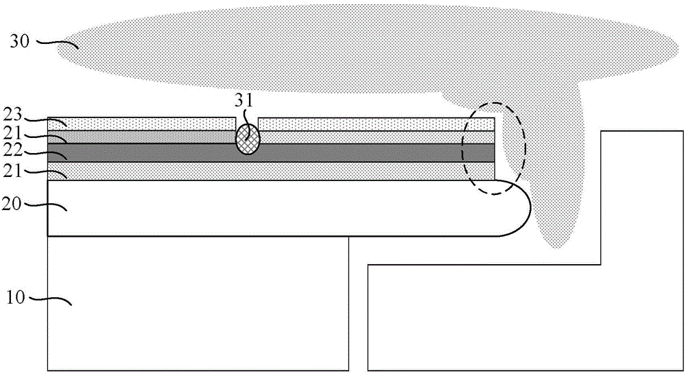
[0005] However, since the photoresist is formed by spin coating, it is usually sprayed on the central area of ​​the wafer 20, and the wafer 20 rotates, and the photoresist is spin-coated from the central area of ​​the wafer 20 to the edge area of ​​the wafer 20 by centrifugal force. Such a formation method inevitably leads to thinner photoresist in the edge region of the wafer 20, and defects are prone to occur during etching, thereby exposing the edge of the metal layer 22 (such as figure 1 shown in the dashed box)
Since the edge of the metal layer 22 is flush with the edge surface of the interlayer dielectric layer 21 in the prior art, the interlayer dielectric layer 21 cannot cover the edge of the metal layer 22, and the etched plasma 30 will contact the metal layer 22. Contact occurs at the edge of the metal layer 22, and the charge will quickly accumulate on the metal layer 22
When the size of the etched window is within a certain range, due to the excessive accumulation of charges, which cannot be released, a discharge phenomenon will occur at the tip of the window, thereby forming a tip discharge defect 31, and then slowly diffuse from the edge of the wafer 20 to the The surface of the entire wafer 20 causes the formation of large-area tip discharge defects, resulting in the scrapping of the wafer 20

Method used


Image

  • Wafer arcing defect avoiding method
  • Wafer arcing defect avoiding method
  • Wafer arcing defect avoiding method

Examples


Embodiment Construction

[0024] The method for avoiding tip discharge defects on wafers of the present invention will be described in more detail below in conjunction with schematic diagrams, wherein a preferred embodiment of the present invention is shown, and it should be understood that those skilled in the art can modify the present invention described here and still realize Advantageous effects of the present invention. Therefore, the following description should be understood as the broad knowledge of those skilled in the art, but not as a limitation of the present invention.

[0025] In the interest of clarity, not all features of an actual implementation are described. In the following description, well-known functions and constructions are not described in detail since they would obscure the invention with unnecessary detail. It should be appreciated that in the development of any actual embodiment, numerous implementation details must be worked out to achieve the developer's specific goals,...


PUM

PropertyMeasurementUnit
Widthaaaaaaaaaa

Abstract

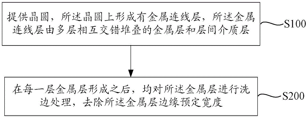
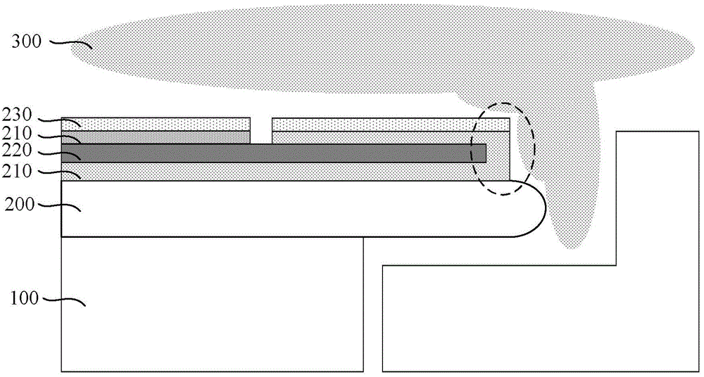
The invention provides a wafer arcing defect avoiding method, which is characterized in that the edge of each metal layer is removed by a predetermined width by adopting edge washing treatment after each metal layer is formed, and the edge of an interlayer dielectric layer can surround the edge of the metal layer, so that the edge of each metal layer is avoided from being exposed, and the edge of each metal layer can be avoided from being directly contacted with plasmas in follow-up etching, thereby reducing accumulation of charge on the metal layers, avoiding generation of an arcing defect, and thus improving the yield of wafers.

Description

technical field [0001] The invention relates to the field of semiconductor manufacturing, in particular to a method for avoiding tip discharge defects on wafers. Background technique [0002] During the wafer preparation process, especially when the metal interconnection line is formed in the back-end process, the etching usually introduces the accumulation of charges. The consequence of excessive charge accumulation is that discharge occurs at the tip, resulting in tip discharge defects ( Arcing defect). The tip discharge defect is very fatal to the wafer, and the occurrence of a small area of ​​defecation will cause the entire wafer to be scrapped. [0003] After the metal interconnection is completed, a passivation layer (PAS) needs to be formed, and then the passivation layer is etched to expose the subsequent metal layer (such as an aluminum pad) that needs to be connected. The tip discharge defect usually occurs after etching the passivation layer. [0004] Specific...

Claims


Application Information

Patent Timeline
IPC IPC(8): H01L21/768H01L23/528
Inventor 陈林郑展
Owner SEMICON MFG INT (SHANGHAI) CORP
Learn More