Multi-mode resonator based dual-mode balun bandpass filter

A band-pass filter, multi-mode resonance technology, applied in the field of microwave passive devices, can solve the problems of large circuit size, large size of balun filter, no longer symmetrical structure, etc., to achieve good matching performance, easy processing and integration, Low insertion loss effect

Active Publication Date: 2016-08-03
NANJING UNIV OF SCI & TECH
View PDF2 Cites 6 Cited by
  • Summary
  • Abstract
  • Description
  • Claims
  • Application Information

AI Technical Summary

Problems solved by technology

Although the design theory of this design method is relatively simple, because the structure introduces a ladder impedance resonator, the bandwidth of the designed balun filter is relatively narrow.
In addition, since the circuit involves three-wire coupling, it is necessary to adopt a zigzag coupling form to enhance the coupling strength between the ladder impedance resonator and the main transmission line, so the structure of the balun filter is more complicated and the circuit size is also larger
[0005] In 2007, Eul-YoungJung and Hee-YongHwang published "ABalun-BPFUsingaDualModeRingResonator" in the IEEE Microwave Wireless Components Letters journal (vol.17, no.9, pp.652-654, 2007), proposing to place two outputs symmetrically on the ring resonator At the same time, an open-circuit stub is introduced to realize the balanced output of the signal and the band-pass characteristic of the dual mode. However, because the structure introduces a step impedance, the structure is no longer symmetrical, resulting in poor balanced output performance of the balun filter. , and since no capacitive loading is introduced, the size of the balun filter is relatively large
Although the balun designed by this design method has the advantage of small size in the low frequency band, it also has the disadvantages of large loss, narrow bandwidth, and poor amplitude and phase matching due to the related characteristics of lumped elements.

Method used


Image

  • Multi-mode resonator based dual-mode balun bandpass filter
  • Multi-mode resonator based dual-mode balun bandpass filter
  • Multi-mode resonator based dual-mode balun bandpass filter

Examples


Embodiment 1

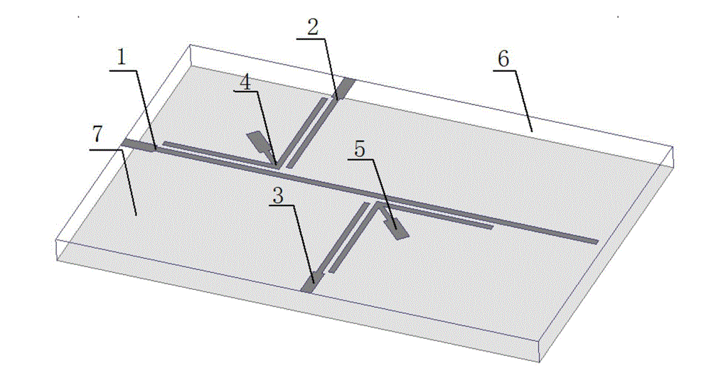
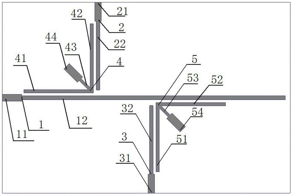
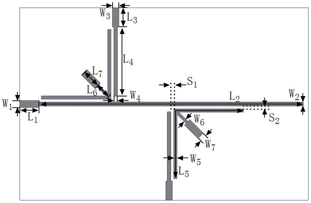
[0028] The structure of a dual-mode balun bandpass filter based on multimode resonators is as follows figure 1 As shown, the top view is as figure 2 As shown, the relevant dimensions and specifications are as follows image 3 shown. The dielectric substrate 7 used has a relative permittivity of 3.38, a thickness of 0.635 mm, and a loss tangent of 0.0035. The characteristic impedance of the 50-ohm microstrip line conduction belt 11 at the input end, the 50-ohm microstrip line conduction belt 21 at the two-port output end, and the 50-ohm microstrip line conduction belt 31 at the three-port output end are all 50 ohms, and the widths are all W 1 = 1.4 mm. combine image 3 , the size parameters of the balun filter are as follows: W 1 = 1.4mm, L 1 = 4mm, W 2 = 1.2mm, L 2 =69mm, W 3 = 1.4mm, L 3 = 4mm, W 4 =0.7mm, L 4 =14.35mm, W 5 =0.7mm,L 5 =28.3mm,W 6 =0.6mm, L 6 = 1.2mm, W 7 =1.6mm, L 7 =2.6mm, S 1 =0.1mm, S 2 = 0.1 mm. The overall area of ​​the balun filter...


PUM


Abstract

The invention discloses a dual-mode balun bandpass filter based on a multi-mode resonator, which includes an input feeder, a two-port output feeder, a three-port output feeder, a first multi-mode resonator, and a second multi-mode resonator device, dielectric substrate, metal ground plate, the first multimode resonator and the second multimode resonator are all multimode resonators loaded on the symmetry plane; the feeder at the input end, the feeder at the two-port output end, and the feeder at the three-port output end , the first multimode resonator and the second multimode resonator are located on the upper surface of the dielectric substrate, and the metal ground plate is located on the lower surface of the dielectric substrate; the first multimode resonator includes two quarter-wavelength resonators, two The symmetrical plane stub loading unit, the second multimode resonator includes two quarter-wavelength resonators and two symmetrical plane stub loading units. The balun bandpass filter of the invention has the advantages of simple structure, low loss, good selectivity and good port matching characteristics, and is very suitable for modern wireless communication systems.

Description

technical field [0001] The invention relates to the technical field of microwave passive devices, in particular to a dual-mode balun bandpass filter based on a multimode resonator. Background technique [0002] In recent years, with the development of Modular Building Block (MBB) and Monolithic Microwave Integrated Circuit (MMIC), low cost, high integration, and miniaturization have become very important considerations in the integrated design of modern wireless communication systems. . In order to achieve these design goals, new passive microwave devices with multifunctional integration features are becoming a research hotspot at home and abroad, and one of the very hot topics is the design of high-performance balun filters. [0003] The balun filter is an independent microwave passive device, which functionally realizes the effective combination of the filter and the balun in the radio frequency circuit, that is to say, the balun filter has both signal filtering and equal...

Claims


Application Information

Patent Timeline
Patent Type & Authority Applications(China)
IPC IPC(8): H01P1/203
Inventor 蔡传涛黄烽林善明顾辉王建朋
Owner NANJING UNIV OF SCI & TECH
Why Eureka
Try Eureka