
Method for manufacturing liquid drop self-driven microreactor and microreactor manufactured through method

A micro-reactor, self-driven technology, applied in chemical instruments and methods, chemical/physical/physical-chemical reactors, chemical/physical/physical-chemical processes, etc. Expensive equipment and other issues to achieve the effect of improving efficiency, simplifying auxiliary equipment, and solving the lack of precision of the flow channel

Active Publication Date: 2016-08-10
ZHEJIANG UNIV OF TECH +1
View PDF5 Cites 22 Cited by
  • Summary
  • Abstract
  • Description
  • Claims
  • Application Information

AI Technical Summary

Problems solved by technology

[0005] Aiming at the disadvantages of the current micro-reaction system, such as expensive production equipment, complex preparation process, and insufficient flow channel accuracy, and most of which require external auxiliary equipment to provide power, the present invention proposes a simple-to-operate microfluidic The self-driven, which greatly reduces the cost of microfluidic drive, has the characteristics of portability, economy, fastness and high efficiency, and has been widely used in related fields such as machine synthesis process, preparation of micron and nanomaterials and production of daily chemicals. Prospect droplet self-driven microreactor preparation method and microreactor

Method used


Image

  • Method for manufacturing liquid drop self-driven microreactor and microreactor manufactured through method
  • Method for manufacturing liquid drop self-driven microreactor and microreactor manufactured through method
  • Method for manufacturing liquid drop self-driven microreactor and microreactor manufactured through method

Examples


Embodiment 1

[0028] Embodiment 1 The preparation method of a kind of droplet self-driven microreactor of the present invention, comprises the following steps:

[0029] 1) Preparation of superhydrophobic titanium dioxide coating solution: mix 0.1g titanium dioxide powder with 10mL absolute ethanol, and then ultrasonicate at 100Hz for 30min to form a 0.01g / mL titanium dioxide suspension, then add 0.2mL octadecyltrimethoxy Silane, continue to ultrasonically mix under the condition of 100Hz, and then react at room temperature for 12h to obtain a superhydrophobic titanium dioxide coating solution; the volume ratio of the octadecyltrimethoxysilane to the titanium dioxide suspension is 0.02:1;

[0030] 2) Preparation of a substrate with a superhydrophobic layer: use a spin coater to spin-coat the superhydrophobic titanium dioxide coating solution onto the cleaned upper surface of the substrate, and then place it in an oven for 1 hour at 100°C to obtain a substrate with a superhydrophobic layer Th...

Embodiment 2

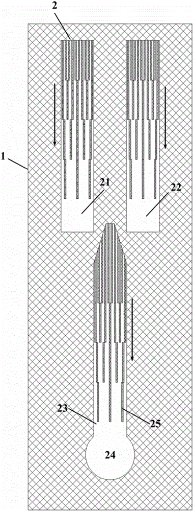
[0037]Example 2 The microreactor constructed according to the preparation method described in Example 1 is characterized in that: it includes a substrate 1 and a hydrophilic-hydrophobic layer 2 coated on the surface of the substrate, and the described hydrophilic-hydrophobic layer is provided with three hydrophilic Water channel, and the three channels are arranged in an "inverted character", of which the two parallel inlet channels in the upper part are 21 and 22, and the channel for transporting the reaction reagents after fusion is 23, and the reagents after the final reaction enter the destination 24; the three hydrophilic flow channels are divided into multiple regions, each region is designed with a number of equidistant super-hydrophobic strip patterns 25, and from the beginning to the end of the flow channel, the super-hydrophobic stripe patterns of adjacent regions The spacing of the hydrophobic strip pattern increases, that is, the proportion of the hydrophilic region...

Embodiment 3

[0038] Embodiment 3 The movement of liquid droplets in a single channel:

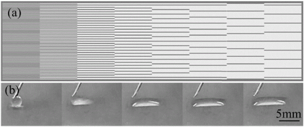
[0039] designed as image 3 The flow channel shown in (a) has a width of 2 mm and a total length of 8 mm. Eight different regions are designed from left to right. The hydrophobic units in each region are 100 μm, and the distance between hydrophobic units gradually increases. , that is, the proportion of the hydrophilic region increases gradually, forming a wetting gradient in the flow channel. After exposure to light, a flow channel that can realize droplet self-driving is obtained. The optical picture of droplet self-driving in the flow channel is as follows: image 3 As shown in (b), a reasonable design of the wetting gradient in the channel can realize the customization of the flow rate.


PUM

PropertyMeasurementUnit
Wavelengthaaaaaaaaaa

Abstract

Provided are a method for manufacturing a liquid drop self-driven microreactor and the microreactor manufactured through the method .The method comprises the steps that 1, super-hydrophobic titanium dioxide coating liquid is prepared; 2, a base body with a super-hydrophobic layer is prepared; 3, a mask plate is manufactured; 4, the microreactor is manufactured .The microreactor manufactured through the method comprises the base body and a hydrophilic-hydrophobic layer smeared to the surface of the base body .According to the hydrophilic-hydrophobic layer, three hydrophilic channels arranged in an inverted three square shape are designed on a hydrophobic coating, the two upper parallel hydrophilic channels on the upper portion are inlet channels of reaction reagents, and the volume ratio of the reaction reagents can be precisely controlled by controlling the distance between the two parallel channels .The two reaction reagents enter the third hydrophilic channel after being combined .The method for manufacturing the liquid drop self-driven microreactor and the microreactor manufactured through the method have the advantages that the problem that the precision of channels is insufficient is solved; self driving of microfluid is achieved, no external auxiliary equipment is needed, and microminiaturization, industrialization and portability of a system can be achieved more easily; the losses of the microfluid in the channels are small, and the efficiency of the microreactor is improved.

Description

technical field [0001] The invention relates to a preparation method of a droplet self-driven microreactor and the microreactor. Background technique [0002] Since the concept of "micro-channel radiator" was first proposed in the 1980s, micro-equipment has entered the chemical and chemical industry with a rapid development attitude. The micro-chemical technology with micro-reaction system as the core is simple, efficient, The advantages of fast flexibility, easy direct amplification and sustainability are favored by the majority of scientific and technological workers and commercial fields. In the past 30 years, based on different methods and purposes, various microreactors have been designed and developed and tried to be applied to various fields. [0003] In recent years, based on the requirements of some specific reactions on the wettability of the surface of the flow channel, the surface wettability has been introduced into the microreactor, and the wettability can be ...

Claims


Application Information

Patent Timeline
IPC IPC(8): B01J19/00
CPCB01J19/0093B01J2219/00894B01J2219/00855B01J2219/0079
Inventor 吴化平刘爱萍丁浩李吉泉柴国钟朱凯曹彬彬吴兵兵
Owner ZHEJIANG UNIV OF TECH
Learn More