Vacuum coating device

A technology of vacuum coating and pulse valve, applied in the direction of gaseous chemical plating, metal material coating process, coating, etc., to solve the problem of gas concentration difference, avoid any dead angle, and improve the effect of deposition speed

Active Publication Date: 2019-05-14
JIANGSU MICROVIA NANO EQUIP TECH CO LTD
View PDF4 Cites 0 Cited by
  • Summary
  • Abstract
  • Description
  • Claims
  • Application Information

AI Technical Summary

Problems solved by technology

Most of the reaction gas is guided to the reaction chamber by top flow or side flow

Method used


Image

  • Vacuum coating device
  • Vacuum coating device
  • Vacuum coating device

Examples


Embodiment 1

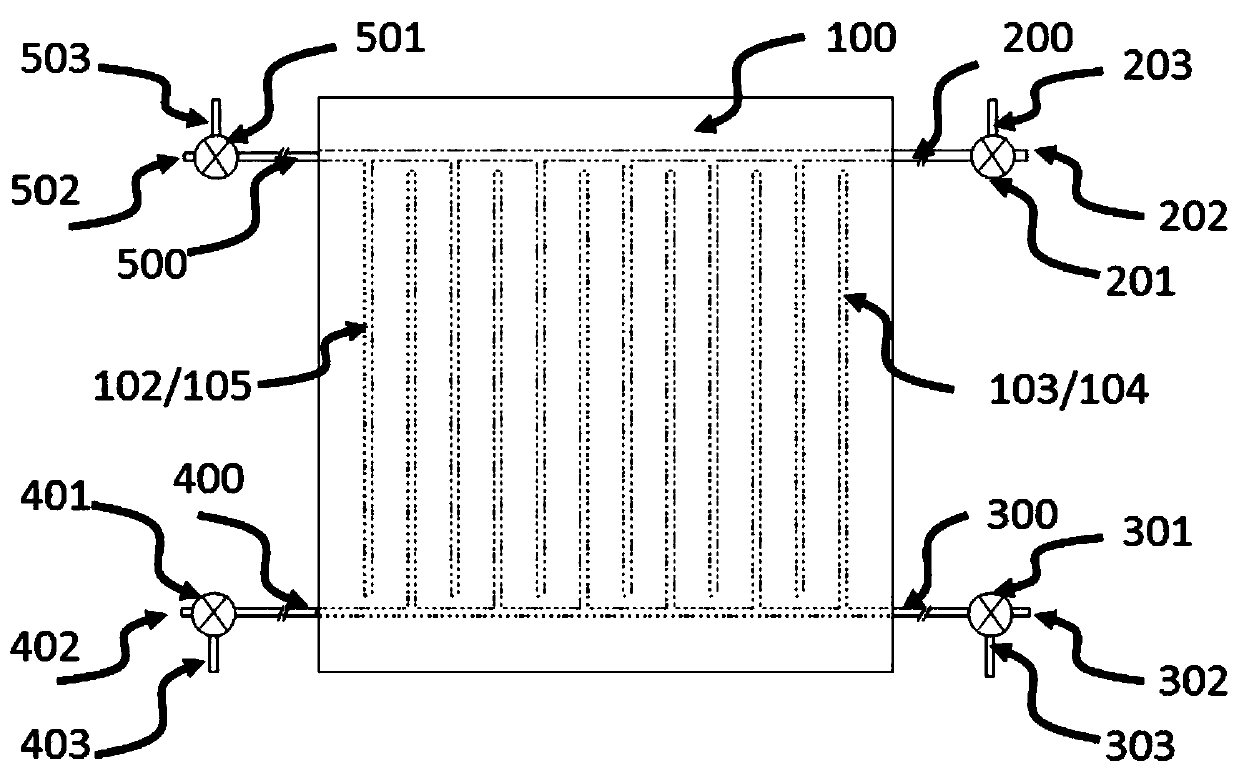
[0075] Figure 3A It is the first embodiment of the patent of the present invention, the gas distribution pipes 102 / 105 / 103 / 104 inside the shower plate 100; the gas distribution pipes 102 / 105 are respectively connected with the gas pipes 200 / 500 of the reaction gas; 104 is respectively connected to the gas pipe 300 / 400 of the reaction gas, and the gas inlet pipe 200 / 300 / 400 / 500 is respectively connected to the three-way pulse valve 201; one port of the three-way pulse valve is connected to the reaction gas 202, and the other port is connected to the inert gas 203 , the third port is connected with the gas inlet pipe 200 / 300 / 400 / 500.

[0076] In this embodiment, the gas inlet pipes 200 / 300 / 400 / 500 and the three-way pulse valves are symmetrically distributed, and the internal gas distribution pipes 102 / 105 / 103 / 104 of the spray plate 100 are arranged crosswise; the gas pipes are provided with two The gas inlet pipes 200 / 500 and 300 / 400, the gas inlet pipe 200 / 500 is a pipe, and ...

Embodiment 2

[0084] Such as Figure 3B As shown, the difference between the second embodiment and the first embodiment is that the intake pulse valve is composed of two two-way pulse valve groups, which include a two-way pulse valve 211 for a reactive gas and a two-way pulse valve 212 for an inert gas; The reaction gas two-way pulse valve 211 of the channel is in the normally closed state, and the reaction gas channel is opened until the end of the pulse time during the pulse; the other inert gas two-way pulse valve 212 for controlling purge can be in the normally open state, and the pulse valve group The controlled reaction gas and the inert gas meet in the external gas inlet pipe before entering the spray plate 100; when one pulse valve controlling the reaction gas channel is opened, the other pulse valves controlling the reaction gas channel are closed.

[0085] In this embodiment, the reactive gas two-way pulse valves 211 , 311 , 411 and 511 have the same structure, and the inert gas t...

Embodiment 3

[0087] Such as Figure 3C As shown, the difference between this embodiment and Embodiments 1 and 2 is that pulse valves with different functions are respectively provided at the two ports of each gas inlet pipe, one end of which is a three-way pulse valve 201, allowing reaction gas and purging The inert gas enters the reaction chamber, and the other end is the suction pulse valve 404. One end of the suction pulse valve 404 is connected to the gas inlet pipe, and the other end is connected to the gas recovery port 406. The suction pulse valve 404 allows part of the reaction gas and the inert gas for purging Suck back to the vacuum pump.

[0088] The gas flow controller 405 is placed in front of the gas inlet pipe of the described suck-back pulse valve 404, and the described suck-back pulse valve 404 can be in a normally open state, or can be in a closed state when the intake pulse valve is opened. The suction pulse valve is open when the air pulse valve is closed.

[0089] Fo...


PUM


Abstract

The invention relates to a vacuum coating device. The device is composed of a spray plate, a reaction cavity communicating with vacuum and a pulse valve. The spray plate serves as a top cover of the reaction cavity at the same time. Gas pipes are arranged in the top cover. Each gas pipe is composed of an external gas inlet pipe and an internal gas distribution pipe, and each gas pipe is independent. According to the technical scheme, the gas inlet pipes and the gas distribution pipes of reaction gas entering the spray plate are completely independent, and therefore it is guaranteed that different kinds of reaction gas are isolated before entering the reaction cavity, CVD is completely avoided, the cleaning time of residual gas reactants and gas reaction products is shortened, and the deposition speed is increased. In addition, gas flow enters the reaction cavity to be evenly distributed, it is ensured that the gas concentration of the reaction gas at any position of the reaction cavity is the same, and the problem of the gas concentration difference influencing the thin film deposition thickness is perfectly solved.

Description

technical field [0001] The invention relates to the technical field of vacuum coating, in particular to a vacuum coating device based on atomic layer deposition. Background technique [0002] Atomic layer deposition (ALD) technology is a thin film deposition technology based on surface chemical vapor phase reaction. Such as Figure 1 As shown, it introduces two or more chemical gas precursors into the reaction chamber separately, so that each precursor undergoes a fully saturated surface chemical reaction on the surface of the substrate, and the gas phase reaction products after the saturated surface reaction and unreacted The gas is purged clean, so the substance can be plated on the surface of the substrate in the form of a monoatomic film, and the thickness and uniformity of the deposited film can be precisely controlled within the atomic layer thickness range. The ALD technology was first called Atomic Layer Epitaxy (ALE), which was proposed by Finnish scientists in the...

Claims


Application Information

Patent Timeline
Patent Type & Authority Patents(China)
IPC IPC(8): C23C16/455
CPCC23C16/45544
Inventor 黎微明左敏李翔胡彬潘景伟
Owner JIANGSU MICROVIA NANO EQUIP TECH CO LTD
Why Eureka
Try Eureka